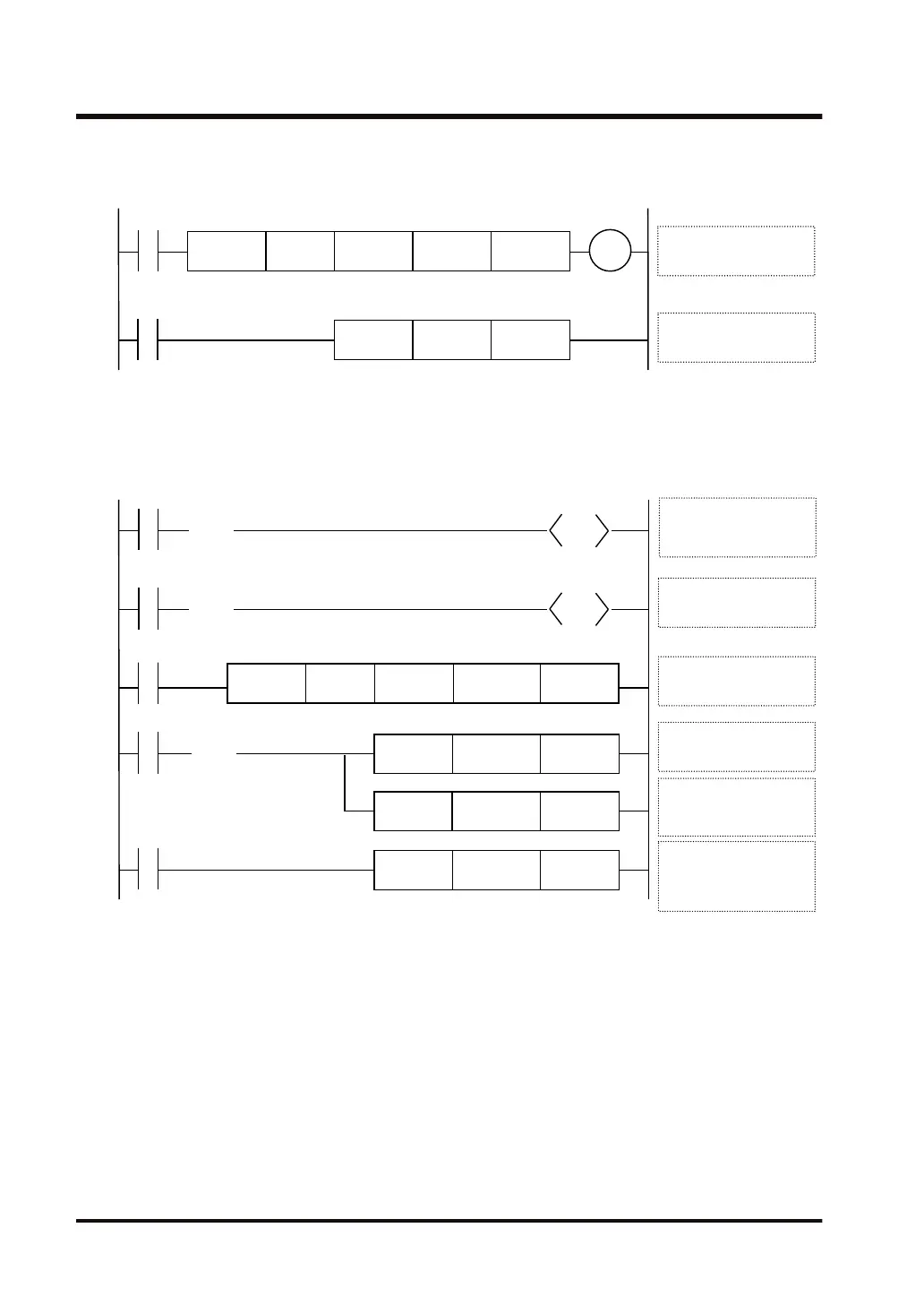
Example) Switch to proportional plus derivative control mode and carry out PWM
output.
R1
EZPID WR1
R1
WX10 DT100 DT0
Y180
MV.US U2 DT5
[S4+5] DT5
Control mode
EZPID instruction
execution
■
Sample program (analog output)
Example) In analog output, change the output upper limit [S4+2] to K4000, and the
control interval [S4+4] to K1000 (10 seconds).
R0
EZPID WR1
R1
WX10 DT100 DT0
MV.SS K4000 DT2
R10
SET
R1
MV.US U1000 DT4
MV.SS DT0 WY18
R1
(( ))
DF
(( ))
DF
R2
R13
SET
(( ))
DF
[S1] WR1 bit3
Select an analog
output
[S1] WR1 bit0
Request auto-tuning
[S4+2] DT2
Output upper limit
[S4+4] DT4
Control interval: 10
seconds
[S4] DT0 WY18
Output value (MV)
Analog output unit
EZPID instruction
execution
● In order to use analog output, set 1 to bit 3 of the operand [S1].
● The output lower limit [S4+1] and the output upper limit [S4+2] should be set according to the
output range of the analog output unit.
● The value of the control interval (Ts): [S4+4] should be modified according to the input
updating interval (normally 0.1 seconds or more) of the analog input unit.
Example) If the value of [S4+4] is K10, Ts is 100 ms.
● Modify other parameters such as the control mode as necessary.
● The manipulated value (MV) stored in the operand [S4] is transferred to the digital value
output area WY that corresponds to the manipulated value of the analog output unit.
● In the manipulated value (MV) of [S4], the output internal calculated value (K0 to K10000) is
converted by the following formula, and stored.
10.12 EZPID (PID Operation: PWM Output Available)
10-50 WUME-FP7CPUPGR-12

 Loading...


