● After auto-tuning is correctly completed, bit 1 of [S1] (auto-tuning completion flag) and the
auto-tuning completion code are stored in [S4+10]. If unsuccessful, the parameters for
proportional gain [Kp], integral time [Ti], and derivative time [Td] are not updated.
● When bit 3 of [S1] is 0 (PWM output), output is carried out in the range from 0 to 10000, with
the duty given by the conversion formula: (Upper limit - Lower limit) x Internal calculated
value / 10000.
● When bit 3 of [S1] is 1 (analog output), the internal calculated value is output in the range
from 0 to 10000, converted by the following formula, and set to the operand [S4] as the
manipulated value (MV). Conversion formula: (Upper limit - Lower limit) x Internal calculated
value / 10000 + Lower limit
■
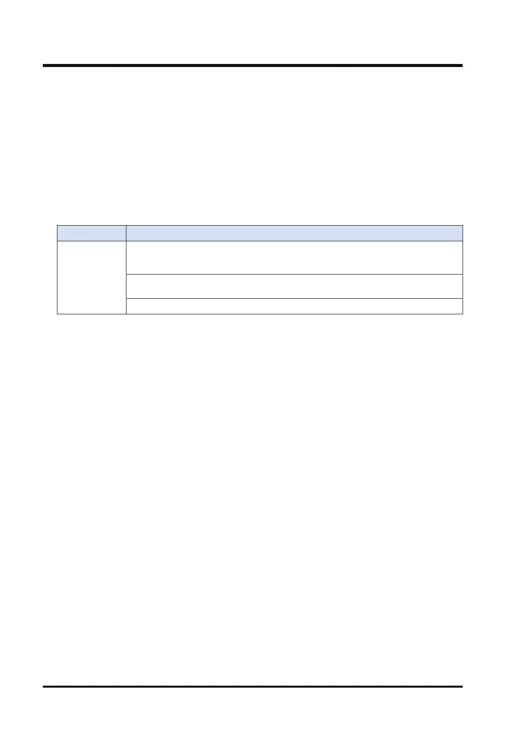
Flag operations
Name Description
SR7
SR8
(ER)
To be set when the following parameters are out of the setting range: [S2]: process value
(PV); [S3]: set point value (SP); [S3]+1: KP; [S3]+2: TI; [S3]+3: TD; and [S4]+4 through
[S4]+9.
To be set when an area specified by [S3] or [S4] exceeds the upper limit of the specified
operation device.
To be set in the case of out-of-range in indirect access (index modification).
10.12 EZPID (PID Operation: PWM Output Available)
10-54 WUME-FP7CPUPGR-12

 Loading...


