(Note 8) Can be specified only when the operation unit is a double-precision floating point real number (DF).
■
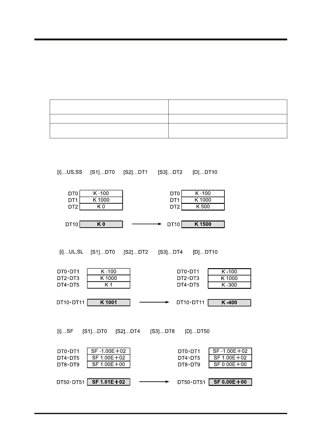
Outline of operation
● The bias value specified by [S1] or [S2] is added to the input value specified by [S3]. The
resulting value is stored in the device address specified by [D].
● Output values are defined as follows:
Input value [S3] < 0 Input value [S3] + Negative bias value [S1] → Output
value [D]
Input value [S3] = 0 0 → Output value [D]
Input value [S3] > 0 Input value [S3] + Positive bias value [S2] → Output
value [D]
■
Processing
Example 1) When the operation unit is 16-bit (US, SS)
Example 2) Operation unit: 32 bits (UL, SL)
Example 3) Operation units: Single precision floating point real number (SF)
10.17 ZONE (Zone Control)
WUME-FP7CPUPGR-12 10-65

 Loading...


