■
Allocation of axis status information to be stored in [D]
bit
Status
information
Axis 1 Axis 2 Axis 3 Axis 4 Virtual axis
0 Tool operation X4 X4 X4 X4 X4
1 Error annunciation X60 X61 X62 X63 X67
2
Warning
annunciation
X68 X69 X6A X6B X6F
3 BUSY X18 X19 X1A X1B X1F
4 Operation done X20 X21 X22 X23 X27
5 Home return done X28 X29 X2A X2B X2F
(Note 1) The I/O numbers in the above table show relative addresses based on the base word number. The I/O
numbers actually used vary according to the slot number where the unit is installed and the starting
word number. Example) The tool operation flag is X104 for slot number 1 if the starting word is number
10.
■
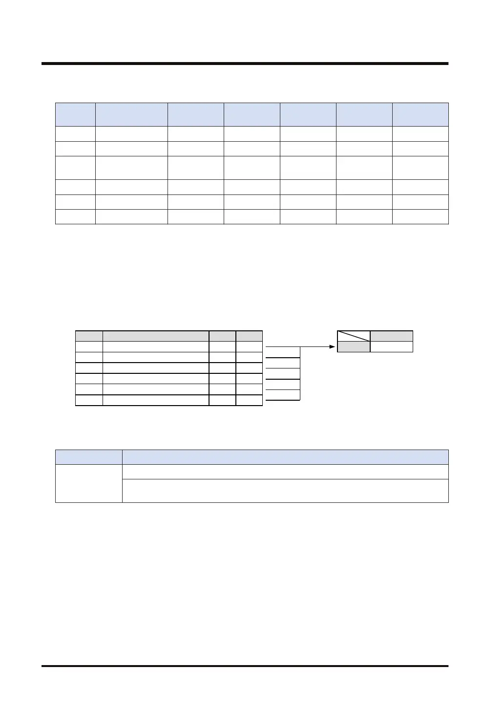
Example of processing
Axis status information for the first axis of the positioning unit attached to slot number 3 is read.
bit Status information Axis 1 Value
0 Tool operation IN4 0
1 Error annunciation IN60 0
2 Warning annunciation IN68 0
3 BUSY IN18 1
4 Operation done IN20 0
5 Home return done IN28 0
Value
DT10 H 0008
■
Flag operations
Name Description
SR7
SR8
(ER)
To be set in the case of out-of-range in indirect access (index modification).
To be set when the slot number and/or the axis number is out of the available range.
13.13 PSTRD (Acquiring Axis Status)
13-22 WUME-FP7CPUPGR-12

 Loading...


