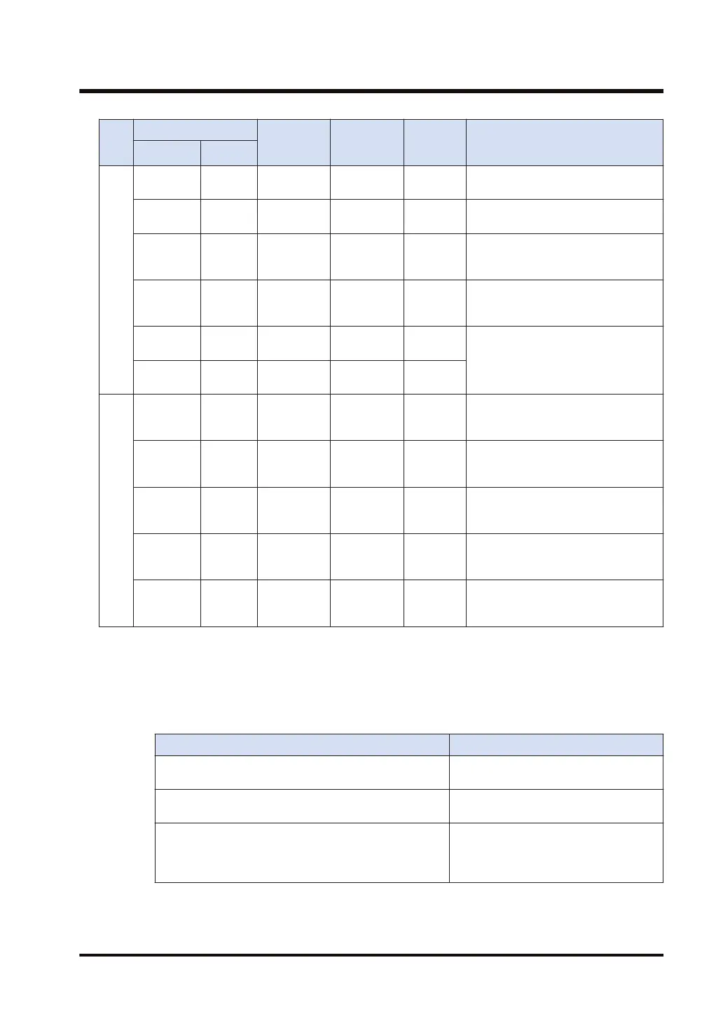
No.
of
bits
Symbol
Name Points Range: Description
Global
Local
DT _DT Data register
Maximum
1M words
0 to
999423
Data memory used in program
LD _LD Link register 16384 words 0 to 16383
Shared data memory used for a PLC
link
UM - Unit memory
Maximum
512 kw/unit
0 to
524287
Device for accessing the unit memory
of an intelligent unit. Its size varies by
unit, and is allocated by default.
SD - System data
Approx. 80
words
-
Data memory for storing specific
data. Various settings and error codes
are stored.
WI - Direct input
Maximum 62
words
0 to 62
Device for input/output processing
during operation in word units,
independent of normal I/O refresh.
WO - Direct output
Maximum 62
words
0 to 62
32
TS _TS
Timer set
value
4096 double
words
0 to 4095
Data memory for storing the target
value of a timer. It corresponds to the
timer number.
TE _TE
Timer
elapsed
value
4096 double
words
0 to 4095
Data memory for storing the elapsed
value of a timer. It corresponds to the
timer number.
CS _CS
Counter set
value
1024 double
words
0 to 1023
Data memory for storing the target
value of a counter. It corresponds to
the counter number
CE _CE
Counter
elapsed
value
1024 double
words
0 to 1023
Data memory for storing the elapsed
value of a counter. It corresponds to
the counter number
I0 to IE -
Index
modification
register
15 double
words
I0 to IE
Register used for modifying memory
area addresses and/or constants.
(Note 1) Figures in the table indicate the number of devices that can be used in a program. The actual number
of input/output points that can be used varies depending on the configuration.
(Note 2) Operation devices are categorized into "hold type", which memorizes the status immediately before
power failure or switch to the PROG. mode, and "non-hold type", which resets the status. Non-hold
area is cleared to zero when the unit is powered on or the mode is switched between PROG and
RUN.
Types of operation devices Setting of hold or non-hold type
Internal relay (R), Data register (DT), Link relay (L), Link
register (LD)
Can be specified as a hold or non-hold
type, using the tool software.
Counter (C), Counter set value (CS), Counter set value
(CE), Error alarm relay (E)
Hold type
Inputs (X), Outputs (Y), Timers (T), Timer set values (TS),
Timer elapsed values (TE), Pulse relays (P), Direct inputs
(IN), Direct outputs (OT), Index registers (I), Unit
memories (UM), System data registers (SD)
Non-hold type
(Note 3) Direct input (IN), direct output (OT), and unit memory (UM) are used by specifying unit slot numbers
and memory addresses to be controlled by instructions.
2.3 Operation device list
WUME-FP7CPUPGR-12 2-13

 Loading...


