■
Sample program (in the case of SCU)
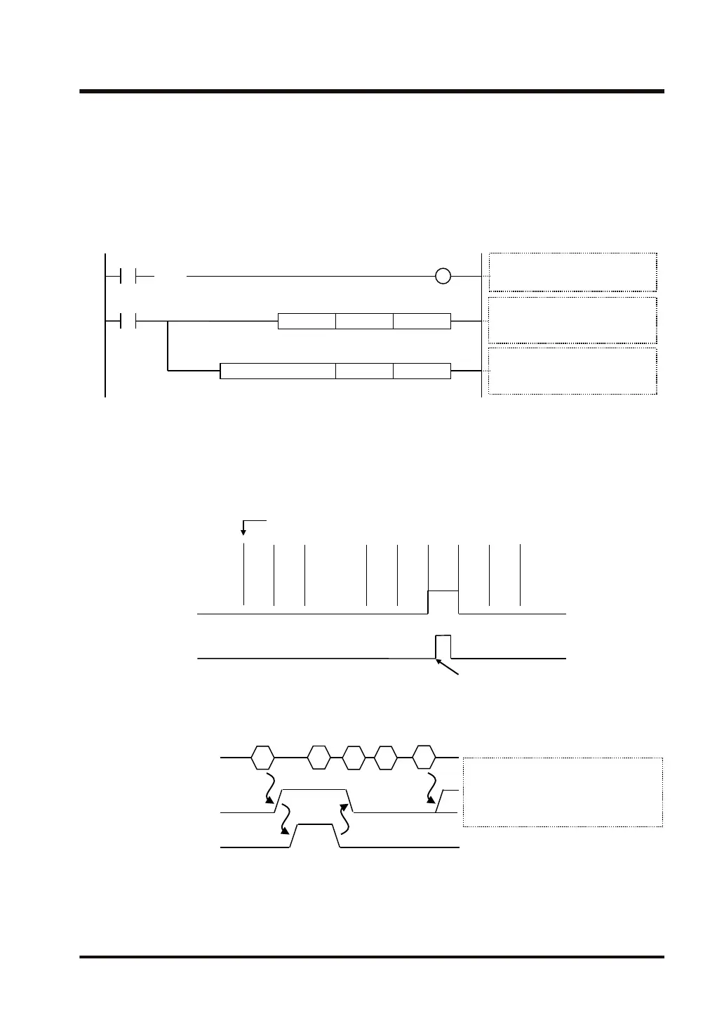
● When the received flag (X0) turns ON, the reception program is started up by the GPRECV
instruction.
● Using the UNITSEL instruction, specify the slot number (U0) and the COM. port number
(U1).
● In the GPRECV instruction, specify and execute the start of the data table that stores the
received message (DT200) and the final address (DT209).
GPRECV .US
DT209DT200
R100
UNITSEL U1U0
GPRECV processing
D1: Header for received data (DT200)
D2: End for received data (DT209)
GPRECV execution condition
Received flag: ON
S1 S2
Communication port settings
S1: Slot 0 built-in CPU (U0)
S2: COM1 (U1)
■
Time chart (in the case of SCU)
● Data received from an external device are stored in the receive buffer.
● When the end code is received, the received flag (X0, X1, X2, X3) turns ON. Subsequently,
the following data are stored in the buffers upon reception. Data for 8 buffers can be received
consecutively.
Start receiving
1Received data
Reception done flag
X0
2
・・・
5 A(
C
R
)
ON
OFF
ON
OFF
GPRECV execution condition
R100
Execute GPRECV instruction
B
・・・
● When the GPRECV instruction is executed, data are copied to the specified area, and the
received flags (X0, X1, X2, X3) are turned OFF. The received flags (X0, X1, X2, X3) are
turned OFF when I/O refresh is executed at the start of the following scans.
Execute GPRECV
Reception done flag
(X0,X1,X2,X3)
Reception done flag (X0,X1,X2,X3):
Reception done: ON,
Received data copy done using
GPRECV instruction: OFF
Cr
Receive buffer
Received data
Cr
15.3 GPRECV (General-Purpose Communication Receive Instruction)
WUME-FP7CPUPGR-12 15-17

 Loading...


