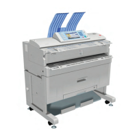
Overview
SM 2-23 D093/D094
Product
Information
NUMBER NAME DESCRIPTION
PCB9 Controller Board
Controls the memory and all peripheral
devices. The GW architecture allows the
board to control all applications (copying,
printing, and scanning).
PCB10 Interface Board
Option. This relay board must be installed with
the external printer controller for interface
between the server PC and the copier.
PCB11 LCDC
LCD control Board. Controls operation of the
operation panel and interfaces with the MCU.
PCB12 Inverter
Provides the background lighting of the LCD
screen on the operation panel.
PCB13 OP-R
Relays the key presses from keys on the right
side of the operation panel to the LCDC
PCB14 OP-L
Relays the key presses from keys on the left
side of the operation panel to the LCDC
PCB15
File Format Converter
(MLB)
Option.
Power Packs
PP1 CGB Power Pack
High voltage power supply for the charge
corona wire (C), development bias (B), and
charge corona grid (G).
PP2 T&S Power Pack
High voltage power supply for the transfer
corona wire (T) and the separation corona
wire (S) in the T&S (Transfer and Separation)
unit.
QL
QL1 - 3
Quenching Lamps:
1: Left, 2: Center, 3:
Right
This removes remaining electrical charge on
the left part of the drum immediately after
cleaning.

 Loading...