3.2
SEL-421 Relay Instruction Manual Date Code 20171021
Testing
Low-Level Test Interface
Step 6. Reconnect the cables removed in Step 4 and replace the relay front-
panel cover.
Step 7. Reconnect any cables previously connected to serial ports on the
front panel.
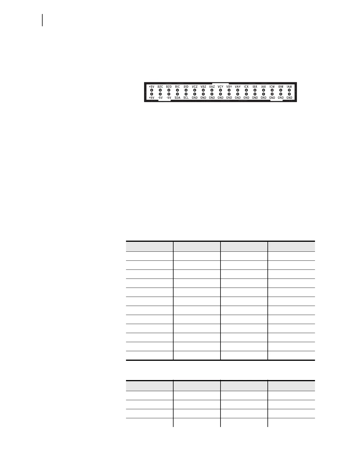
Use signals from the SEL-4000 Low-Level Relay Test System to test the relay
processing module. Apply appropriate signals to the low-level test interface J24
from the SEL-4000 Relay Test System (see Figure 3.1). These signals simulate
power system conditions, taking into account PT ratio and CT ratio scaling. Use
relay metering to determine whether the applied test voltages and currents pro-
duce correct relay operating quantities.
The UUT Database entries for the SEL-421 in the SEL-5401 Relay Test System
Software are shown in Table 3.1 and Table 3.2.
Figure 3.1 Low-Level Test Interface
Table 3.1 UUT Database Entries for SEL-5401 Relay Test System Software—5 A
Relay
Label Scale Factor Unit
1 IAW 75 A
2 IBW 75 A
3 ICW 75 A
4 IAX 75 A
5 IBX 75 A
6 ICX 75 A
7VAY150V
8VBY150V
9VCY150V
10 VAZ 150 V
11 VBZ 150 V
12 BCZ 150 V
Table 3.2 UUT Database Entries for SEL-5401 Relay Test System Software—1 A
Relay (Sheet 1 of 2)
Label Scale Factor Unit
1 IAW 15 A
2 IBW 15 A
3 ICW 15 A
4 IAX 15 A
U.S. Patent 5,479,315
Input Module Output (J3): 66.6 mV At Nominal Current (1 A or 5 A)
446 mV at Nominal Voltage (67 V
LN
)
Processing Module Input (J24): 6.6 Vp-p Maximum