5.165
Date Code 20171021 Instruction Manual SEL-421 Relay
Protection Functions
Synchronism Check
Voltages V
P
, V
S1
, and V
S2
are used in the logic in the balance of this section to
check for healthy voltage and determine voltage phase angle for synchronism-
check element operation.
Voltage Checks and Blocking Logic
Two conditions can cause the synchronism-check function in the SEL-421 to
abort. These conditions are out-of-range synchronism-check input voltages and
block synchronism check configurations that you specify in SEL
OGIC control
equations.
Voltage Magnitude Checks (Applicable When E25BK
n
= Y or Y2)
For synchronism check to proceed for a given circuit breaker (BK1 or BK2)
when E25BKn = Y or Y2, the voltage magnitudes of the synchronism-check volt-
age reference V
P
and the corresponding normalized synchronism-check voltage
source on the other side of the circuit breaker (normalized voltage V
S1
for Circuit
Breaker BK1 and normalized voltage V
S2
for Circuit Breaker BK2) must lie
within a healthy voltage window, bounded by voltage threshold settings 25VH
and 25VL (see Figure 5.125).
The relay asserts Relay Word bits 59VP, 59VS1, and 59VS2 to indicate healthy
synchronism-check voltages V
P
, V
S1
, and V
S2
, respectively (see Figure 5.125). If
either of the voltage pairs (V
P
and V
S1
or V
P
and V
S2
) does not meet this healthy
voltage criterion, synchronism check cannot proceed for the circuit breaker asso-
ciated with the corresponding voltage pair.
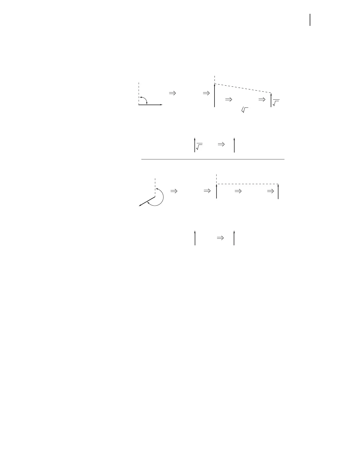
Figure 5.124 Normalized Synchronism-Check Voltage Sources VS1 and VS2
(b)
(a)
V
BC
V
BC
∠90˚
∠90˚
∠240˚∠240˚
∠240˚
∠90˚
Synchronism-check
Voltage Source 1
Synchronism-check
Voltage Source 2
No effective
magnitude adjustment
Adjusted for angle
Adjusted for angle
Normalized synchronism-check
Voltage Source 1
Adjusted for magnitude
(=1 )
Apply
KS1A := 90
Apply
KS2A := 240
Apply
KS1M := 0.58
Apply
KS2M := 1.00
3
90˚
V
S1
V
BC
3
Normalized synchronism-check
Voltage Source 2
V
S2
3
V
C
V
C
V
C
240˚
V
C
V
BC