5.164
SEL-421 Relay Instruction Manual Date Code 20171021
Protection Functions
Synchronism Check
For a given secondary base voltage, phase-to-phase voltages are a factor of 1.73
(3) times the magnitude of the phase-to-neutral voltages. In reverse, phase-to-
neutral voltages are a factor of 0.58 (1/3) times the magnitude of the phase-to-
phase voltages. Therefore, you must compensate the Bus 1 voltage V
BC
magni-
tude with setting KS1M to reference it to the synchronism-check voltage refer-
ence V
P
magnitude.
KS1M := 0.58. Synchronism Source 1 Ratio Factor (0.10–3)
You do not need special magnitude compensation for the Bus 2 voltage V
C
to ref-
erence Synchronism Source 2 to the synchronism-check voltage reference V
P
magnitude; these are both phase-to-neutral voltages with the same nominal rating
(for example, 67 V secondary).
KS2M := 1.00. Synchronism Source 1 Ratio Factor (0.10–3)
As another example of synchronism-source magnitude adjustment flexibility,
suppose Bus 1 voltage V
BC
is 201 V secondary (phase-to-phase), and the syn-
chronism-check voltage reference V
P
is 67 V secondary (phase-to-neutral). Then,
the magnitude compensation setting would be as in Equation 5.32.
Equation 5.32
Normalized Synchronism-Check Voltage Sources VS1 and VS2
The Figure 5.123 example continues in Figure 5.124, which graphically illus-
trates how the introduced settings adjust the Bus 1 and Bus 2 synchronism-check
input voltages in angle and magnitude to reference to the synchronism-check
voltage reference V
P
. The resultant Bus 1 and Bus 2 voltages are the normalized
synchronism-check voltage sources V
S1
and V
S2
, respectively.
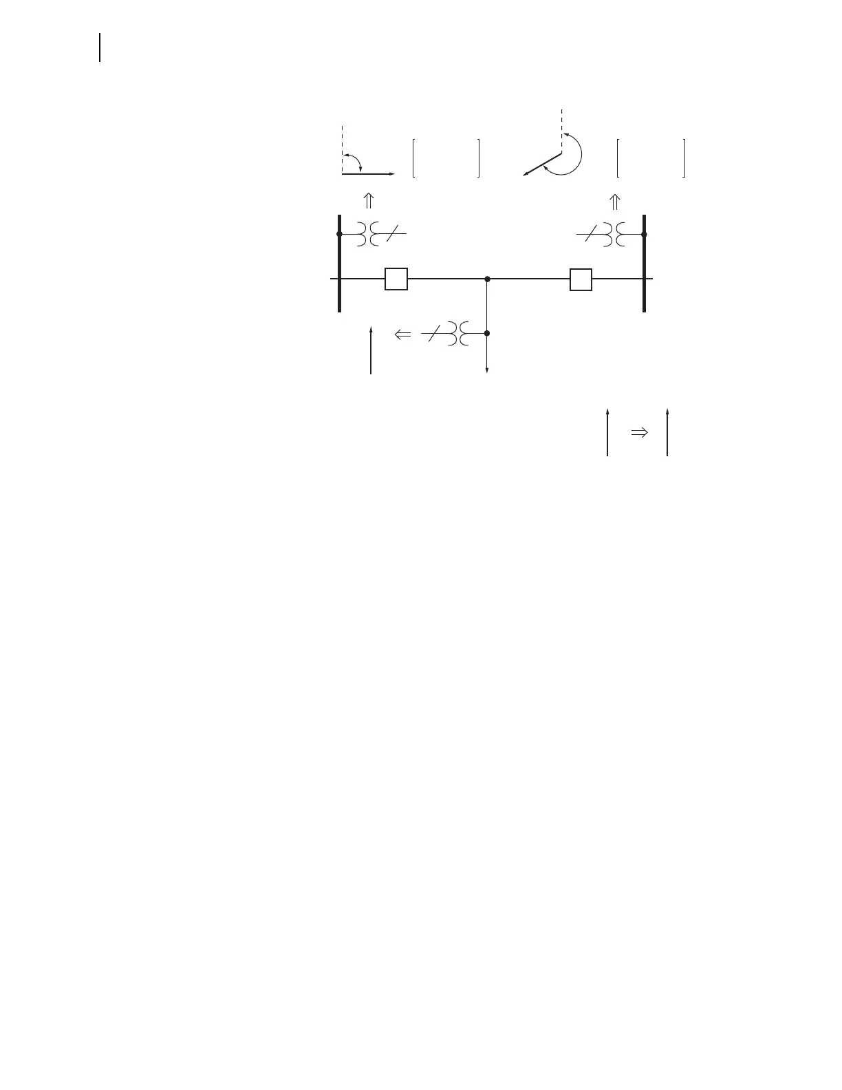
Figure 5.123 Synchronism-Check Voltage Reference
V
BC
Voltage V
BC
Connected to
Voltage Input VAZ
Voltage V
C
Connected to
Voltage Input VBZ
SYNCS1 := VAZ
KS1M := 0.58
KS1A := 90
90˚
V
C
240˚
V
A
V
A
V
P
SYNCS2 := VBZ
KS2M := 1.00
KS2A := 240
Bus 2
Bus 1
Line
BK2
BK1
Synchronism-Check
Voltage Reference
Voltage V
A
connected to
Voltage Input VAY (other 2
three-phase line voltages not
shown). Voltage Input VAY
designated as synchronism-check
voltage reference by setting SYNCP := VAY.
1
3
1
. . . . . .
KS1M
67 V
201 V
--------------- 0.33:= =