3.3
Date Code 20171006 Instruction Manual SEL-400 Series Relays
Basic Relay Operations
Establishing Communication
The serial number label does not list power system phase rotation and frequency
ratings, because you can use relay settings to configure these parameters. The
factory defaults are ABC phase rotation and 60 Hz nominal frequency. See Mak-
ing Settings Changes in Initial Global Settings on page 3.20 for details on setting
these parameters.
Logic Input Ratings
The serial number label in Figure 3.1 only lists control input voltages for I/O
Interface Boards that have optoisolated inputs, which is determined at ordering
time. The other types of control inputs (Direct Coupled) have settable pickup
voltages, and do not appear on the serial number label. See Control Input Assign-
ment on page 3.69 for more information.
Establishing Communication
Once you have applied the correct power input successfully, you are ready to
operate the relay. Use the relay front panel and the communications ports to com-
municate with the relay.
Front-panel control of relay functions involves use of a menu system that you
access through the LCD and the six navigational pushbuttons shown in
Figure 3.2. For complete instructions on using the front-panel menu system, see
Front-Panel Menus and Screens on page 4.14.
Fast and efficient communication with the relay is available through communica-
tions ports such as PORT F, also shown in Figure 3.2. A design philosophy for all
SEL relays is that an ASCII or open terminal is all that you need to communicate
with the relay. Many off-the-shelf computer programs provide terminal emula-
tion. These programs are inexpensive and widely available.
Use the cable connections appropriate for your terminal configuration. See
Section 15: Communications Interfaces for more information on communica-
tions ports.
All ASCII commands you send to the relay must terminate with a carriage return
or carriage return/line feed; the terminal emulation program appends the neces-
sary carriage return when you press <Enter>.
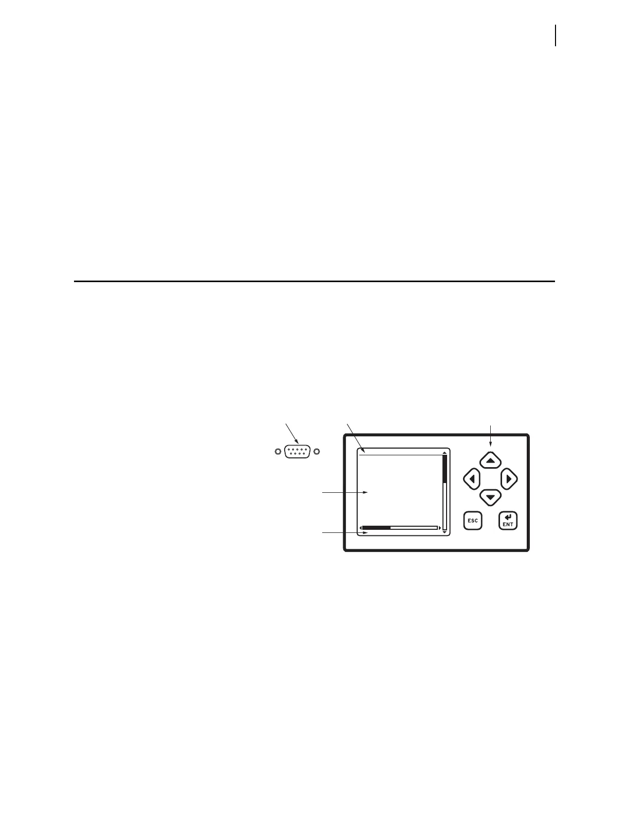
Figure 3.2 PORT F, LCD Display, and Navigation Pushbuttons
Navigation
Pushbuttons
Title
Area
Serial
Communications Port
LCD Display Main Area
PORT F
Message Area
5 4 3 2 1
9 8 7 6