5.47
Date Code 20171021 Instruction Manual SEL-421 Relay
Protection Functions
CVT Transient Detection
Level 1 and Level 2 directional overcurrent element directions are fixed in the
forward direction for residual ground and negative-sequence directional overcur-
rent elements. Level 3 and Level 4 residual and negative-sequence directional
overcurrent elements (67Q3, 67Q4, 67G3, and 67G4) share the same direction as
the corresponding zones of distance protection, also using settings DIR3 and
DIR4.
This directional control option is performed in addition to the regular torque con-
trol settings for each element (the torque control setting acts as a supervisory
input).
The phase directional overcurrent elements (67P1–67P4) and the selectable oper-
ating quantity time-overcurrent elements (51S1–51S3) do not have any built-in
directional control. The torque control settings (67P1TC, 67P2TC, 67P3TC,
67P4TC, 51S1TC, 51S2TC, 51S3TC) can be used to achieve directional control,
as shown in the 230 kV Overhead Distribution Line Example on page 6.1.
CVT Transient Detection
The SEL-421 detects CVT (Capacitor Voltage Transformer) transients that can
cause Zone 1 distance elements to overreach during external faults. If CVT tran-
sient blocking is enabled and the relay detects a high SIR (source-to-impedance
ratio) when a Zone 1 distance element is picked up, the relay delays tripping for
as long as 1.5 cycles to allow the CVT transients to stabilize.
You do not need to enter settings. The relay adapts automatically to different sys-
tem SIR conditions by monitoring the measured voltage and current.
If the distance calculation does not change significantly (i.e., is smooth), the
SEL-421 unblocks CVT transient blocking resulting from low voltage and low
current during close-in faults driven by a source with a high SIR. Therefore, Zone
1 distance elements operate without significant delay for close-in faults.
Consider using CVT transient detection logic when you have either of the follow-
ing two conditions:
➤ SIR greater than or equal to five
➤ CVTs with AFSC (active ferroresonance-suppression circuits)
The following conditions can aggravate CVT transients:
➤ CVT secondary with a mostly inductive burden
➤ A low C value CVT, as defined by the manufacturer
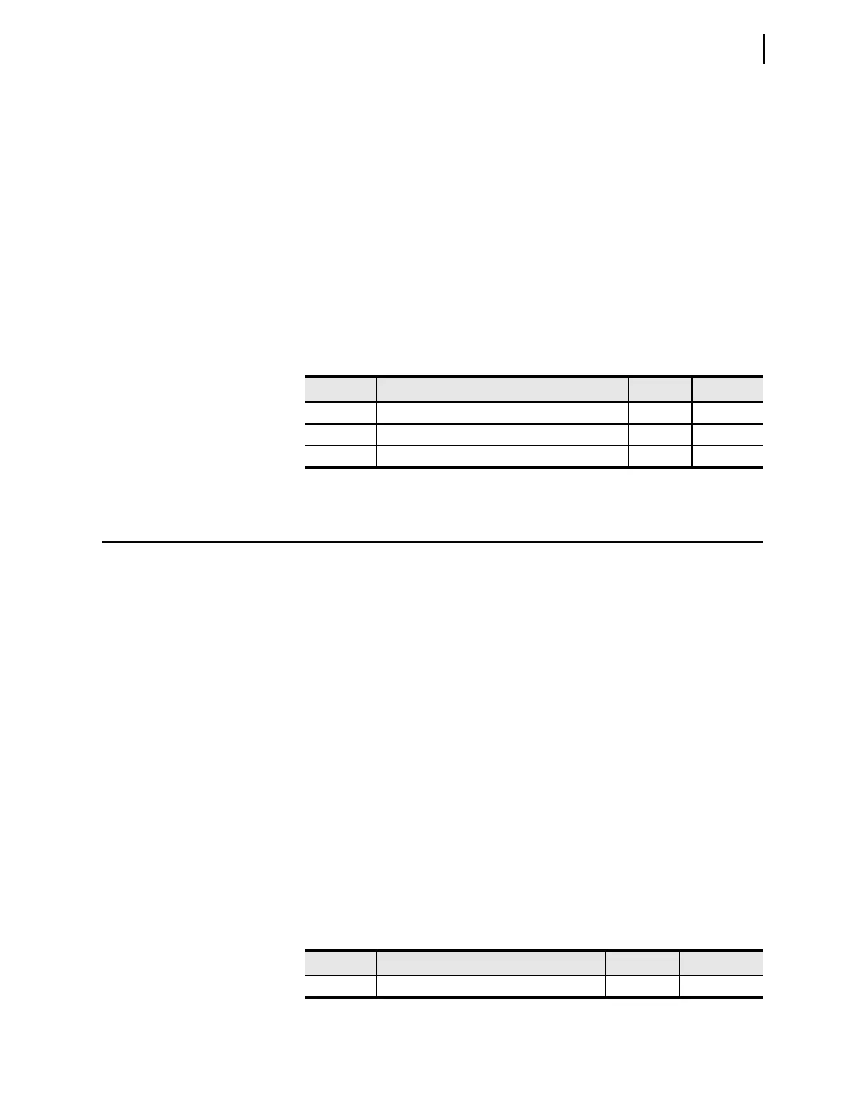
Table 5.40 Zone Directional Settings
Setting Prompt Range Default
DIR3 Zone/Level 3 Directional Control F, R R
DIR4 Zone/Level 4 Directional Control F, R F
DIR5 Zone/Level 5 Directional Control F, R F
Table 5.41 CVT Transient Detection Logic Setting
Setting Prompt Range Default
ECVT CVT Transient Detection Y, N N