2.5
Date Code 20171021 Instruction Manual SEL-421 Relay
Installation
Shared Configuration Attributes
Secondary Circuits
The SEL-421 is a very low burden load on the CT secondaries and PT secondar-
ies. For both the CT and PT inputs, the frequency range is 40–65 Hz.
The relay accepts two sets of three-phase currents from power system CT inputs:
➤ IAW, IBW, and ICW
➤ IAX, IBX, and ICX
For 5 A relays, the rated nominal input current, I
NOM
, is 5 A. For 1 A relays, the
rated nominal input current, I
NOM
, is 1 A.
Input current for both relay types can range to 20 • I
NOM
.
See AC Current Inputs (Secondary Circuits) on page 1.14 for complete CT input
specifications.
The relay also accepts two sets of three-phase, four-wire (wye) potentials from
power system PT or CCVT (coupling-capacitor voltage transformer) secondaries:
➤ VAY, V B Y, a n d V C Y
➤ VAZ, VBZ, and VCZ
The nominal line-to-neutral input voltage for the PT inputs is 67 volts with a
range of 0–300 volts. The PT burden is less than 0.5 VA at 67 volts, L-N. See AC
Voltage Inputs on page 1.14 for complete PT input specifications.
Some applications do not use all three phases of a source; for example, voltage
synchronization sources can be single phase. See Section 6: Protection Applica-
tions Examples for examples of connections to the potential inputs.
See Secondary Circuit Connections on page 2.34 for information on connecting
power system secondary circuits to these inputs.
Relays that use the TiDL system do not contain secondary circuits on the relay.
The secondary circuit uses a remote SEL-2240 Axion to supply the voltages and
currents through a direct fiber link; however, the nominal current must be
selected to appropriately apply scaling through various protection functions. The
relay, by default, assumes 5 A as the nominal current selection. For 1 A scaling,
use the CFG CTNOM command (see Table 14.28 on page 14.10 in the SEL-400
Series Relays Instruction Manual for more information). The SEL-2245-42 AC
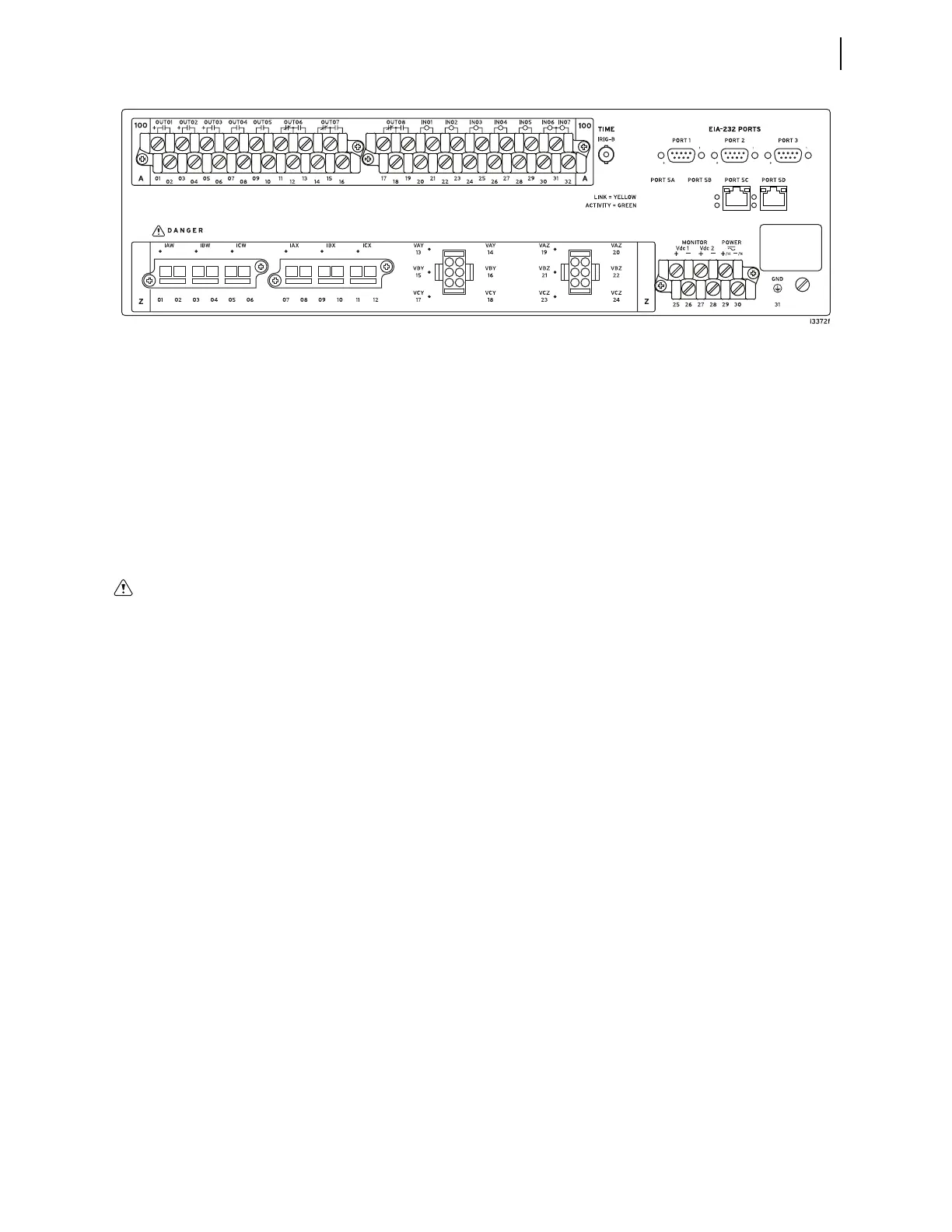
(In a vertical-mount relay, the right rear side is at the top.)
Figure 2.3 Rear 3U Template, Connectorized Analog Inputs
Before working on a CT circuit, first
apply a short to the secondary wind-
ing of the CT.