6.75
Date Code 20171021 Instruction Manual SEL-421 Relay
Protection Applications Examples
345 kV Tapped Overhead Transmission Line Example
32V Reverse Directional Check
You set Z0MAG equal to Z
0L1
plus Z
0L2
so the fault locator provides correct
results for internal faults not located on the tap (that is, source T is extremely
weak and provides practically no infeed).
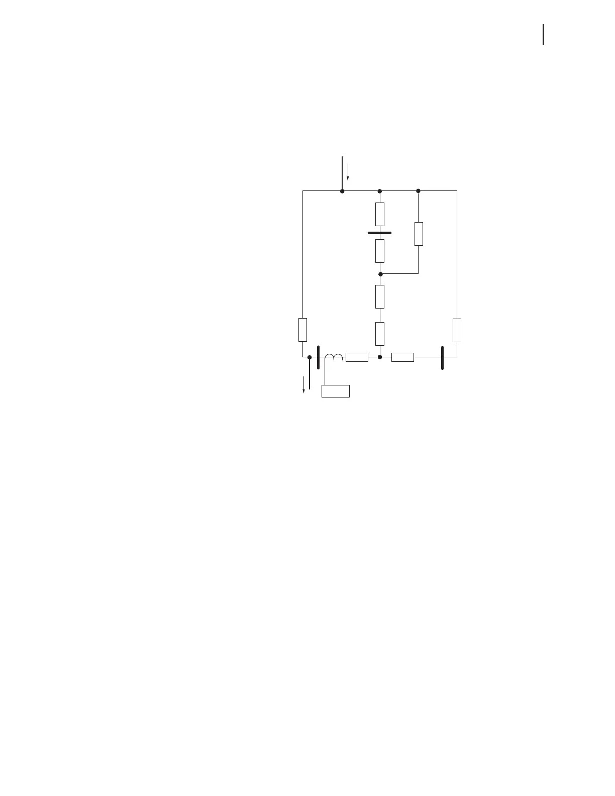
Figure 6.17 is the zero-sequence network for the 345 kV tapped overhead transmission
line.
If z0 is less than Z0F during a reverse unbalanced fault, 32V incorrectly declares
that the fault is forward with respect to the relay location (CT shown in
Figure 6.17). The relay automatically sets Z0F equal to one-half Z0MAG.
Equation 6.47 is the apparent zero-sequence impedance measured by 32V during
reverse unbalanced faults:
Equation 6.47
Equation 6.48
Use the following two assumptions to simplify the calculations:
1. Assume the power system is purely reactive
2. Ignore source impedances Z
0R
and Z
0T
(a conservative assumption)
Figure 6.17 345 kV Tapped Line Zero-Sequence Network
where:
Z
0P
= parallel combination of the Line 3 impedance, transformer
high-side reactance (neglect resistance), and the parallel com-
bination of the transformer low-side and Bus T impedance in
parallel with the transformer tertiary impedance, in parallel
with Line 2 and the Bus R impedance (see Figure 6.17).
where:
Z
0PP
= the parallel combination of the transformer low-side and Bus T
impedance in parallel with the transformer tertiary impedance
Z
0T
Z
M
Z
L
Z
H
S
Z
0L3
Z
0L2
Z
0L1
I
O
I
O
Z
0R
Z
0S
R
T
SEL-421
Z
0P
Z
0L3
jX
H
Z
0PP
++Z
0L2
Z
0R
+
=