2.25
Date Code 20171021 Instruction Manual SEL-421 Relay
Installation
Connection
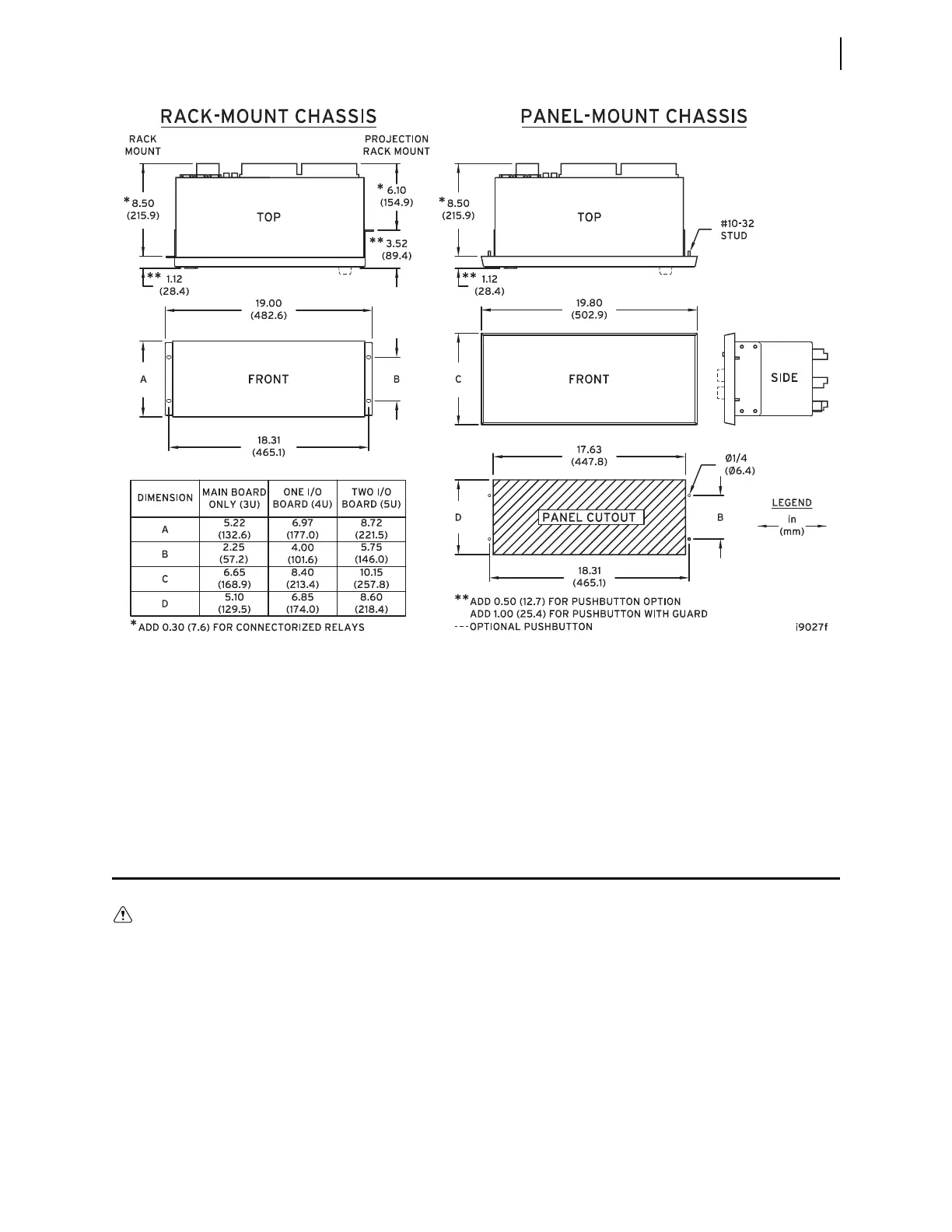
Panel Mounting
Place the panel-mount versions of the SEL-421 in a switchboard panel. See the
drawings in Figure 2.22 for panel cut and drill dimensions (these dimensions
apply to both the horizontal and vertical panel-mount relay versions). Use the
supplied mounting hardware to attach the relay.
Connection
The SEL-421 is available in many different configurations, depending on the
number and type of control inputs, control outputs, and analog input termination
you specified at ordering. This subsection presents a representative sample of
relay rear-panel configurations and the connections to these rear panels. Only
horizontal chassis are shown; rear panels of vertical chassis are identical to hori-
zontal chassis rear panels for each of the 3U, 4U, and 5U sizes.
When connecting the SEL-421, refer to your company plan for wire routing and
wire management. Be sure to use wire that is appropriate for your installation
with an insulation rating of at least 90°C.
Figure 2.22 SEL-421 Chassis Dimensions
Insufficiently rated insulation can
deteriorate under abnormal operating
conditions and cause equipment dam-
age. For external circuits, use wiring
of sufficiently rated insulation that
will not break down under abnormal
operating conditions.