7.10
SEL-421 Relay Instruction Manual Date Code 20171021
Metering, Monitoring, and Reporting
Reporting
Figure 7.2 contains selected data from the analog section of a 4-samples/cycle
event report for a BCG fault on a 400 kV line with CT ratio := 400/1 and PT
ratio := 3636/1. The bracketed numbers at the left of the report (for example,
[11]) indicate the cycle number; Figure 7.2 presents seven cycles of 4-samples/
cycle data.
The trigger row includes a > character following immediately after the V1Mem
column to indicate the trigger point. This is the dividing point between the pre-
fault or PRE time and the fault or remainder of the data capture.
The row that the relay uses for the currents in the event summary is the row with
the largest current magnitudes; the relay marks this row on the event report with
an asterisk (*) character immediately after the V1Mem column. The (*) takes
precedence over the > if both occur on the same row in the analog section of the
event report.
Digital Section of the Event Report
The second portion of an event report is the digital section. Inspect the digital
data to evaluate relay element response during an event. See Figure 7.3 for the
locations of items in a sample event report digital section. If you want to view
only the digital portion of an event report, use the EVE D command (see EVE D
on page 14.24 in the SEL-400 Series Relays Instruction Manual for details). In
the digital portion of the event report, the relay indicates deasserted elements
with a period (.) and asserted elements with an asterisk (*) character.
The element and digital information labels are single character columns. Read
these columns from top to bottom. The trigger row includes a > character follow-
ing immediately after the last digital element column to indicate the trigger point.
The relay marks the row used to report the maximum fault current with an aster-
[10]
-126 4616 -6204 -1714 -282.9 178.6 41.9 216.4 143.5 -222.1
-106 4288 -1047 3135 -231.6 -64.5 95.3 -289.4 331.9 -162.6
65 -1722 1878 221 140.2 -72.1 -43.6 -216.6 -143.3 194.6
16 -807 4 -786 105.1 41.3 10.5 289.2 -332.0 130.7
Circuit Breaker Open
[11]
-1 -1 -2 -5 13.8 1.1 0.3 216.8 143.1 -147.1
2 3 4 9 54.8 -0.7 -0.3 -289.1 332.1 -93.5
1 1 2 5 -8.1 -1.6 -1.1 -217.0 -142.8 109.8
-2 -2 -3 -8 -58.2 0.2 0.2 289.0 -332.2 65.3
Figure 7.2 Fixed Analog Section of the Event Report (Continued)
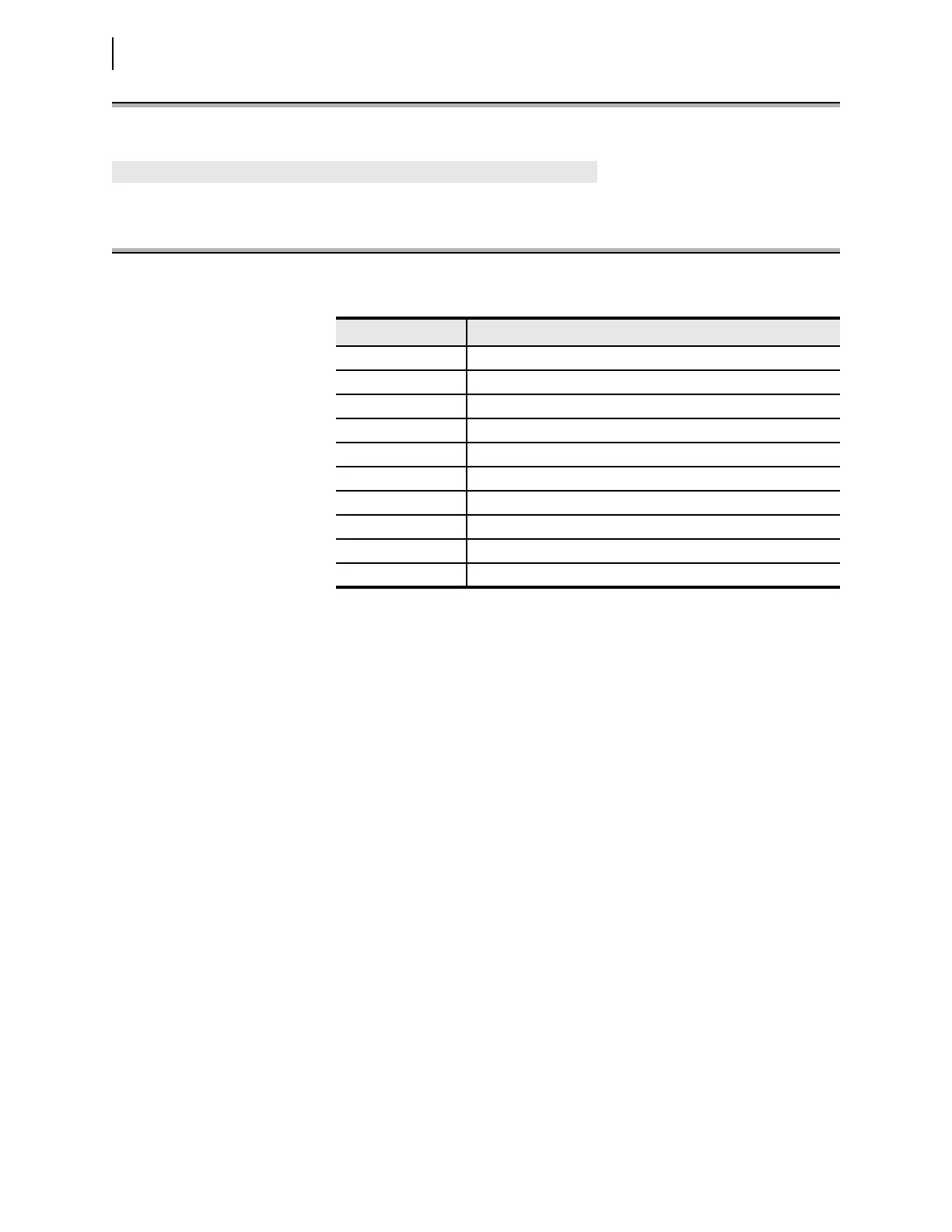
Table 7.9 Event Report Metered Analog Quantities
Quantity Description
IA Instantaneous filtered line current, A-Phase
IB Instantaneous filtered line current, B-Phase
IC Instantaneous filtered line current, C-Phase
IG Instantaneous filtered line current, residual (or ground)
VA Instantaneous filtered A-Phase voltage
VB Instantaneous filtered B-Phase voltage
VC Instantaneous filtered C-Phase voltage
VS1 Instantaneous filtered synchronization Source 1 voltage
VS2 Instantaneous filtered synchronization Source 2 voltage
V1Mem Instantaneous memorized positive-sequence polarization voltage

 Loading...


