2.36
SEL-421 Relay Instruction Manual Date Code 20171021
Installation
Connection
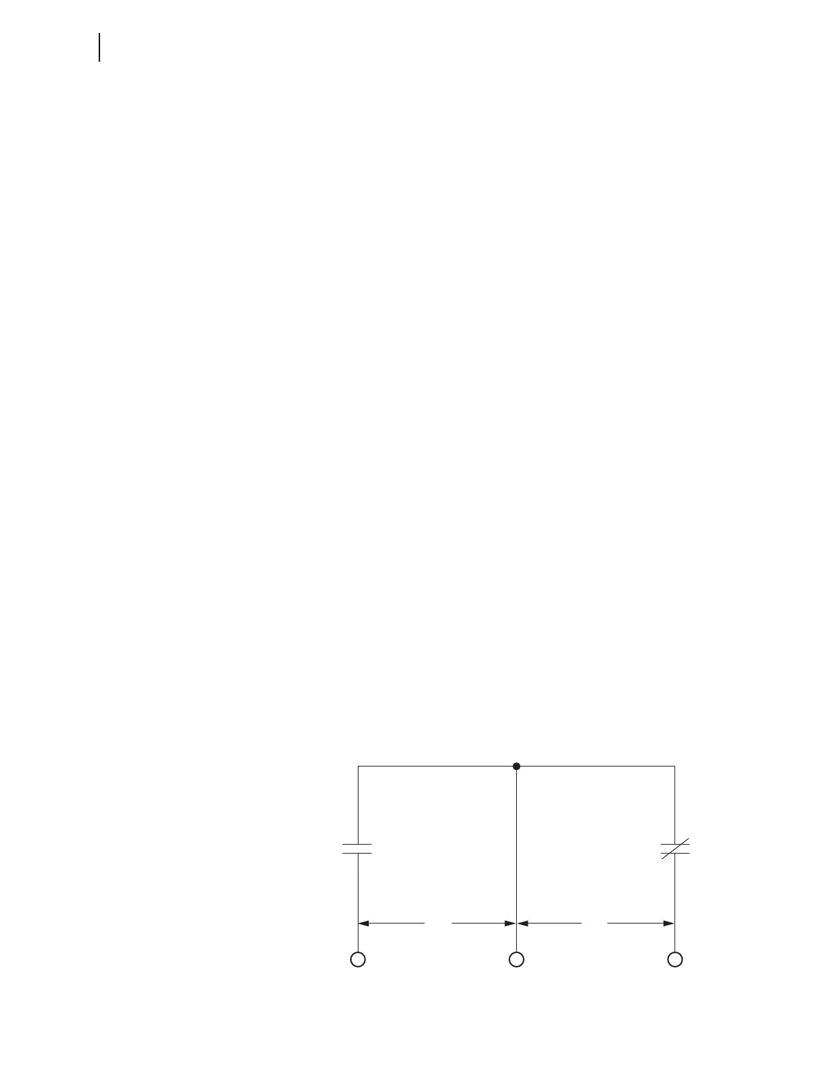
Note that the main board I/O control inputs have one set of two inputs that share
a common input leg and INT3 and INT4 I/O interface boards have two sets of
nine inputs that share a common leg (see Figure 2.13).
Assigning
To assign the functions of the control inputs, see Operating the Relay Inputs and
Outputs on page 3.61 in the SEL-400 Series Relays Instruction Manual for more
details. You can also use
ACSELERATOR QuickSet SEL-5030 Software to set and
verify operation of the inputs.
Control Outputs
The SEL-421 has three types of outputs:
➤ Standard outputs
➤ Hybrid (high-current interrupting) outputs
➤ High-speed, high-current interrupting outputs
See Control Outputs on page 2.8 for more information.
You can connect the standard outputs and the high-speed, high-current interrupt-
ing outputs in either ac or dc circuits. Connect the hybrid (high-current interrupt-
ing) outputs to dc circuits only. The screw-terminal connector legends alert you
about this requirement by showing polarity marks on the hybrid (high-current
interrupting) contacts.
Form A (SPST NO) contacts comprise the majority of the control outputs. Two
pairs of Form C (SPDT CO) contacts are on the main board, the INT1 (INT2) I/O
interface board, and the INT6 (INT7) I/O interface board.
Alarm Output
The SEL-421 monitors internal processes and hardware in continual self-tests. If
the relay senses an out-of-tolerance condition, the relay declares a Status Warn-
ing or a Status Failure. The relay signals a Status Warning by pulsing the
HALARM Relay Word bit (hardware alarm) to a logical 1 for five seconds. For a
Status Failure, the relay latches the HALARM Relay Word bit at logical 1.
To provide remote alarm status indication, connect the b contact of OUT108 to
your control system remote alarm input. Figure 2.37 shows the configuration of
the a and b contacts of control output OUT108.
Figure 2.37 Control Output OUT108
N/O N/C
COUT108
OUT108
ab
(connect alarm here)