5.19
Date Code 20171021 Instruction Manual SEL-421 Relay
Protection Functions
Over- and Underfrequency Elements
Case 2: Single-Phase PT Input, Connected to the A-Phase Input
In this case, VF01 = VA, VF02 = ZERO, and VF03 = ZERO.
Equation 5.7
Equation 5.8
Set 81UVSP to 60 percent of this value:
Equation 5.9
Equation 5.10
Case 3: Single-Phase PT Input, Connected to the B- or C-Phase Input
In this case, VF01 = ZERO, VF02 = VB, and VF03 = ZERO.
Equation 5.11
Equation 5.12
Set 81UVSP to 60 percent of this value:
Equation 5.13
Equation 5.14
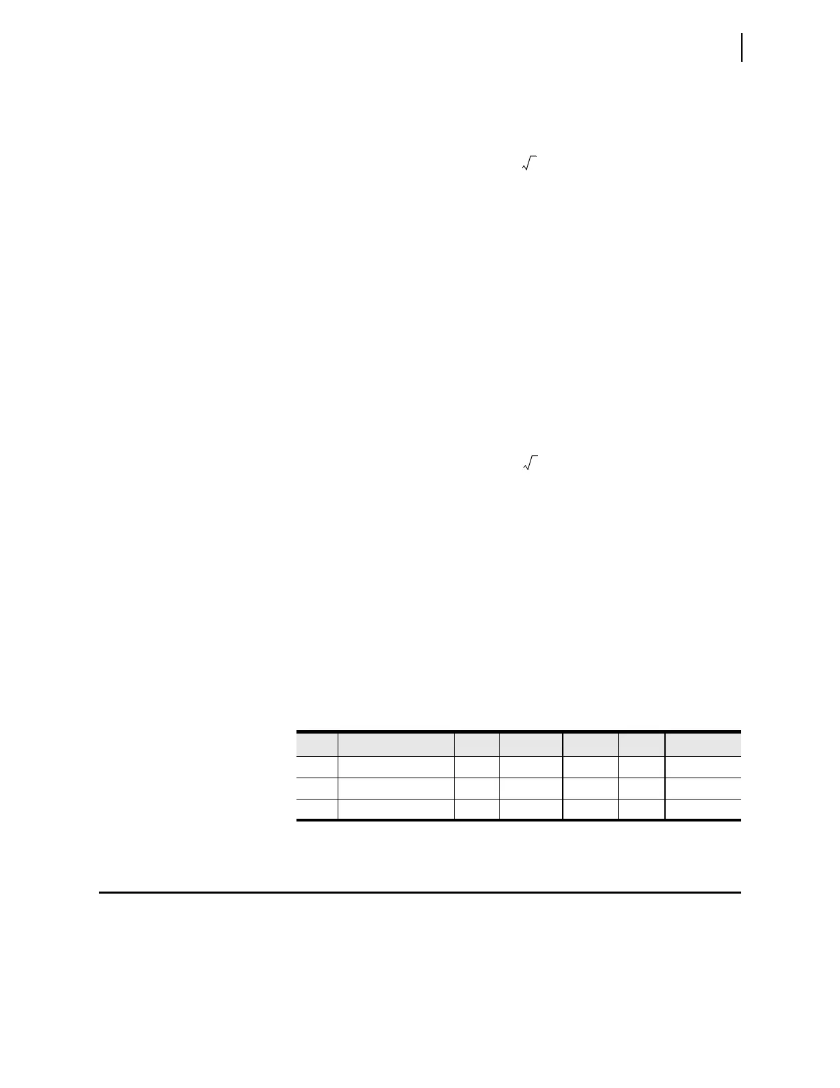
Table 5.17 summarizes the results of the three cases.
Over- and Underfrequency Elements
Use the relay frequency elements for such abnormal frequency protection as
underfrequency load shedding.
Figure 5.15 shows the logic for the six levels of over- and underfrequency ele-
ments in the relay.
Table 5.17 Table Y12. Summary of the Valpha and 81UVSP Calculations
Case PT Connections VA VB VC Valpha 0.6 • Valpha
Case 1 Three-phase 67 0° 67 –120° 67 120° 142.13 85.28
Case 2 Single-phase, VA 67 0° 0 0 94.75 56.85
Case 3 Single-phase, VB/VC 0 67 –120° 0 47.38 28.43