5.173
Date Code 20171021 Instruction Manual SEL-421 Relay
Protection Functions
Synchronism Check
NOTE: If the relay is using a remote
data acquisition system, such as TiDL,
the operating times will be delayed by
1.5 ms. Use caution when setting the
relay for synchronism check to
account for this added delay.
Element 25A1BK1 follows V'
S1
. With setting 25SFBK1 (maximum slip fre-
quency) set to other than OFF, the relay calculates V'
S1
derived from V
S1
. Phasor
V'
S1
leads V
S1
by an angle described by Equation 5.33:
Equation 5.33
From Equation 5.33 note that the angle between V
S1
and V'
S1
increases for a
greater slip between V
S1
and V
P
(f
S1
–f
P
), a greater Circuit Breaker BK1 close
time setting TCLSBK1, or both in combination.
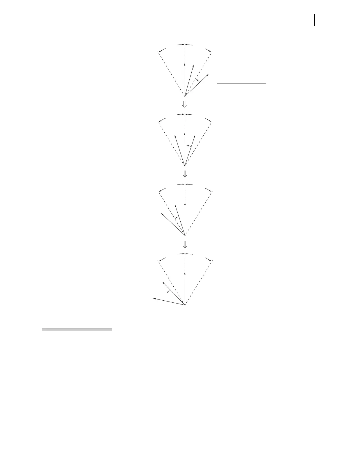
Figure 5.130 “Slip—With Compensation” Synchronism-Check Element Output
Response
V
P
(a)
(b)
(c)
(d)
V
S1
V'
S1
V
P
V
S1
V
P
V
S1
V
P
V
S1
Response of synchronism-check
element outputs (Relay Word Bits):
25W1BK1 = logical 1
25A1BK1 = logical 1
25W1BK1 = logical 1
25A1BK1 = logical 0
25W1BK1 = logical 0
25A1BK1 = logical 0
25W1BK1 = logical 0 (follows V
S1
)
25A1BK1 = logical 0 (follows V'
S1
)
A
N
G
1
B
K
1
A
N
G
1
B
K
1
A
N
G
1
B
K
1
A
N
G
1
B
K
1
A
N
G
1
B
K
1
A
N
G
1
B
K
1
A
N
G
1
B
K
1
A
N
G
1
B
K
1
V'
S1
V'
S1
V'
S1
Slip (asynchronous systems—not paralleled).
Max slip frequency setting 25SFBK1 other than OFF
angle
f
S1
f
P
– slip cycle
s
60 cyc
s
-----------------•
-------------------------------------------------
360
slip cycle
------------------------
TCLSBK1 (cyc)• • =