2.6
SEL-421 Relay Instruction Manual Date Code 20171021
Installation
Shared Configuration Attributes
Analog Input Module also sets its internal calculations based on this command.
The relay internally transmits these data to the Axion modules and adjusts the
appropriate scaling in the Axion module when this command is used.
In addition to the CT nominal values, TiDL relays also require you to set the
nominal frequency by issuing the CFG NFREQ command. At Access Level 2,
issue a CFG NFREQ 60 command to set the relay to 60 Hz nominal or issue a
CFG NFREQ 50 command to set the relay to 50 Hz nominal. This command
changes the NFREQ setting and restarts the relay, and it is only available in TiDL
relays. The relay defaults to 60 Hz, so only use this command if you want to
switch to 50 Hz nominal. Issue this command after the CFG CTNOM command
but before sending settings to the relay.
Control Inputs
Direct Coupled
NOTE: The SEL-421 INT1, INT5, and
INT6 I/O interface boards have
polarity-sensitive inputs, and the
terminals are identified with a polarity
mark.
The SEL-421 inputs on the optional I/O interface boards (INT1, INT5, or INT6
I/O boards—see Models and Options on page 1.5), are direct-coupled, high-
impedance control inputs. Use these inputs for monitoring on/off and logical
change-of-state conditions of power system equipment. These high-isolation con-
trol inputs are polarity-sensitive circuits. You cannot damage these inputs with a
reverse polarity connection, although the relay will not detect input changes with
a reverse-polarity input. For more information on control input specifications, see
Control Inputs on page 1.15.
Inputs can be independent or common. Independent inputs have two separate
ground-isolated connections to a high-isolation analog-to-digital converter
(ADC). There are no internal connections among independent inputs. Common
inputs share one input leg in common; all input legs of common inputs are
ground-isolated. Each pair of common inputs is isolated from all other pairs.
Nominal current draw for these inputs is very low (4 mA or less) with an input
voltage range of 15 Vdc to 265 Vdc. You can adjust the level at which these
inputs assert (and deassert) and can also debounce the control inputs. See Global
Settings on page 8.2 for the default settings and more information.
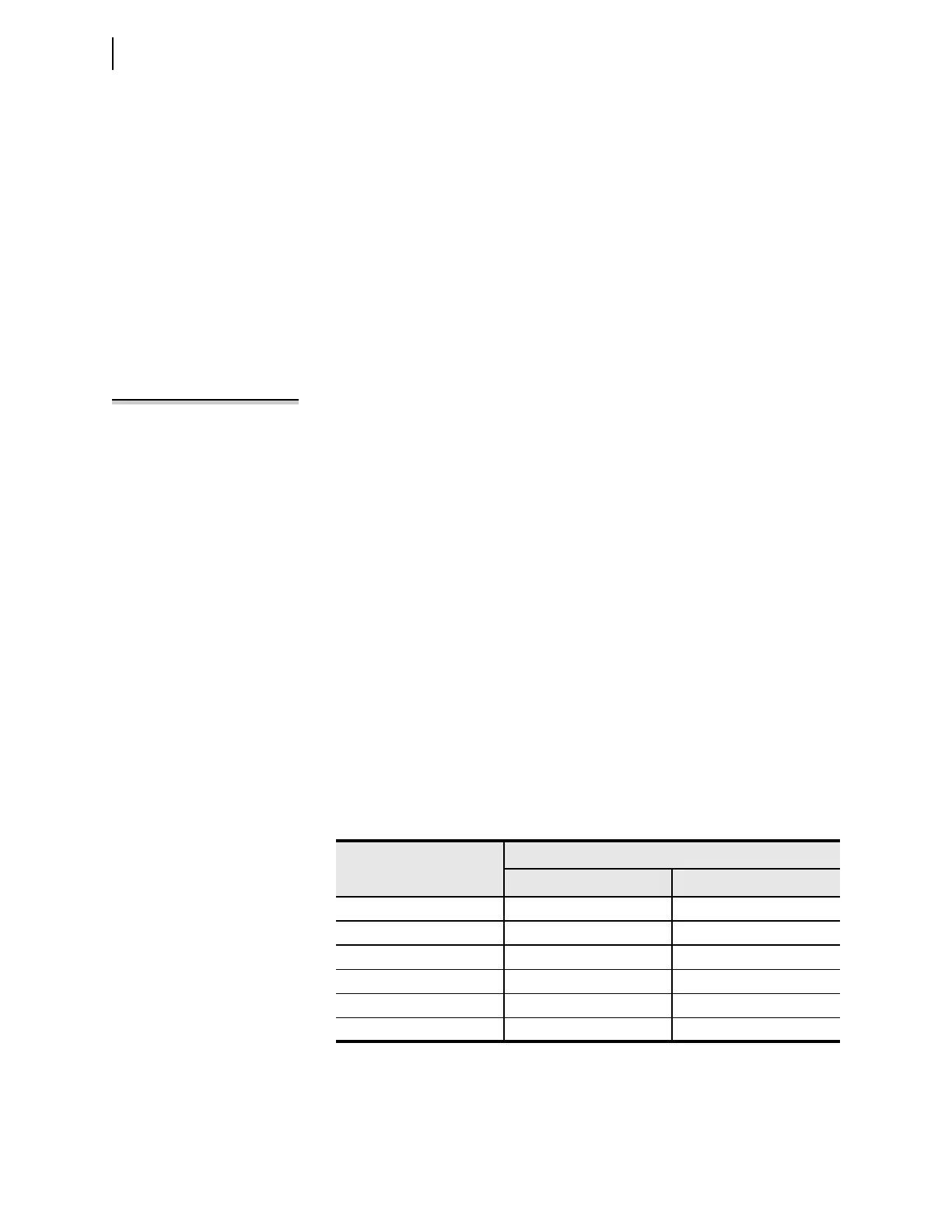
To ensure secure performance of the control inputs, set the control input pickup
level according to the battery voltage level. Tabl e 2.1 lists some of the common
DC voltage levels and appropriate settings.
Table 2.1 Recommended Control Input Pickup Settings
Substation DC Voltage
Level
Recommended Settings
Pickup: GINP
a
a
Applies to IN2
nn
P and IN3
nn
P when global setting EICIS := N.
Dropout: GINDF
24 18 Vdc 85%
48 36 Vdc 85%
110 88 Vdc 80%
125 100 Vdc 80%
220 176 Vdc 80%
250 200 Vdc 80%