6.45
Date Code 20171021 Instruction Manual SEL-421 Relay
Protection Applications Examples
500 kV Parallel Transmission Lines With Mutual Coupling Example
Assign these two permissive signals to the first two Transmit MIRRORED BITS
signals.
TMB1A := KEY1 OR EKEY AND RMB1A. Transmit MIRRORED BITS 1A
(SEL
OGIC Equation)
TMB2A := KEY3 OR EKEY AND RMB2A. Transmit MIRRORED BITS
2A(SEL
OGIC Equation)
Receive Equations
Any type of fault detected within Zone 2 at Station R transmit KEY1, which is
converted to PT1 at Station S through the M
IRRORED BITS pair, TMB1A and
RMB1A. The SEL-421 at Station S can high-speed single-pole trip via the com-
munications channel if the fault type is identified as single-phase and single-pole
tripping is enabled, regardless of fault selection at the remote terminal.
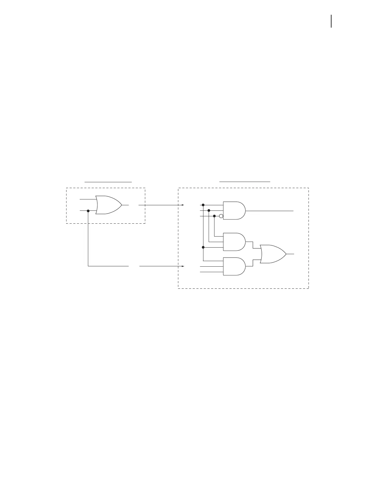
Figure 6.10 is a simplified logic diagram for the communications-assisted trip-
ping logic.
If the SEL-421 at Station S detects a multiphase fault in Zone 2, it can high-speed
three-pole trip only if both PT1 and PT3 assert. PT3 confirms that the remote ter-
minal (Station R) has also identified the fault type as multiphase. If the SEL-421
detects a multiphase fault in Zone 2 and receives only PT1, like in the cross-
country fault situation on a parallel-line system, the relay delays a trip until the
permissive signal received agrees with the fault type detected locally. The fault
type detected by the SEL-421 at Station S changes from a multiphase to a single-
phase ground fault after Station R clears the external fault on line 2. The relay can
then single-pole trip via the received PT1. Note that a desired single-pole trip at
Station S occurs only after Station R clears the external fault on line 2. To avoid a
delayed trip in a cross-country fault situation, you may choose the three-channel
POTT scheme (POTT3), as described below.
Two Relay Word bits identify receipt of trip permission:
➤ PT1—General permission to trip received
➤ PT3—Three-pole permission to trip received
Figure 6.10 Simplified POTT Scheme KEY1/KEY3 Logic
KEY1
Local Station (Station R)
KEY3
Z2G
PT1
PT3
Z2G
TMB2A RMB2A
RMB1ATMB1A
Z2P
E3PT
SPT
3PT
Z2P
Remote Station (Station S)