6.154
SEL-421 Relay Instruction Manual Date Code 20171021
Protection Applications Examples
Circuit Breaker Failure Application Examples
Scheme 2
Relay Word bit FBF1 (Breaker 1 Breaker Failure) asserts for these conditions:
➤ A single phase-to-ground fault occurs: FBF1 asserts when time delay
on pickup timers BFPU1 (Breaker Failure Time Delay—BK1)
followed by SPBFPU1 (SPT Breaker Failure Time Delay—BK1)
expire. The corresponding 50FP1 element and only one single-
phase breaker failure initiation (for example, BFIA1) are asserted.
➤ A multiphase fault occurs: FBF1 asserts when time delay on pickup
timer BFPU1 (Breaker Failure Time Delay—BK1) expires. The
corresponding 50F1 elements and at least two single-phase breaker
failure initiations (for example, BFIA1 and BFIB1) are asserted.
Timing Sequence
Figure 6.40 and Figure 6.41 illustrate the timing sequence for circuit breaker fail-
ure schemes.
Scheme 1
Scheme 1 follows Figure 6.40.
Scheme 2
Scheme 2 uses both timing sequences in Figure 6.40 and Figure 6.41, depending
on the fault type (multiphase fault and single-phase fault, respectively).
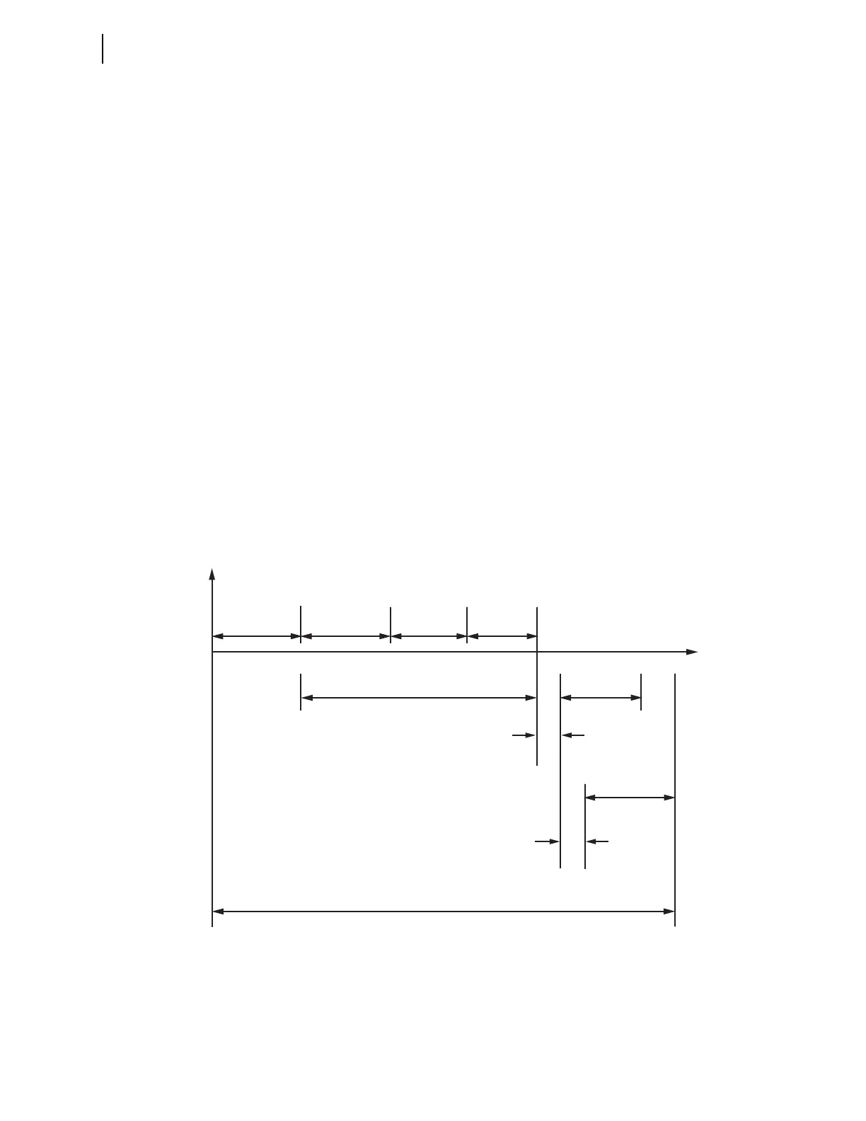
Figure 6.40 Scheme 1 All Faults and Scheme 2 Multiphase Fault Timing Diagram
50Fφn Element
Asserts
Transfer
Trip
Asserts
BF Trip
Outputs
Assert
BF Timer Delay (BFPU)
Communications Channel Time
Absolute Maximum Fault Clearing Time
t
Local Backup
Breakers Trip
Time
Remote Breakers
Trip Time
Protective Relay
Operate Time
Maximum Breaker
Operating Time
50Fφn
Dropout Time
Safety Margin
Time
Fault Occurs
Trip Asserts
Normal
Operation
Breaker
Failure
Operation
Auxiliary Breaker Failure
Relay Operate Time