8.38
SEL-421 Relay Instruction Manual Date Code 20171021
Settings
Report Settings
The SEL-421 contains all of the selectable screen choices listed in Table 12.29 on
page 12.18 in the SEL-400 Series Relays Instruction Manual except DIFF_L,
DIFF_T, DIFF, and ZONECFG.
Report Settings
The SEL-421 contains the report settings described in Report Settings on
page 12.23 in the SEL-400 Series Relays Instruction Manual except that the
SEL-421 does not support HIF event reports.
The rows containing the following elements are always included as part of the
100 rows of event reporting digital elements: TLED_1, TLED_2, TLED_3,
TLED_4, TLED_5, TLED_6, TLED_7, TLED_8, TLED_9, TLED_10,
TLED_11, TLED_12, TLED_13, TLED_14, TLED_15, TLED_16, SPOA,
SPOB, SPOC, FSA, FSB, FSC, Z1P, Z2P, Z3P, Z4P, Z5P, 67Q1, 67Q2, 67Q3,
67Q4, 51S1, 51S2, 51S3, Z1G, Z2G, Z3G, Z4G, Z5G, 67G1, 67G2, 67G3, 67G4,
RMBnA, TMBnA, RMBnB, TMBnB, ROKA, RBADA, CBADA, LBOKA,
ROKB, RBADB, CBADB, LBOKB, TRIP TP1, TP2, 52CL1, 52CL2,
BK1CL, BK2CL (n = 1–8, = A,B,C). For row descriptions see Section 11:
Relay Word Bits.
Port Settings
The SEL-421 port settings are as described in Port Settings on page 12.6 in the
SEL-400 Series Relays Instruction Manual.
The fast message read data access settings listed in Table 12.8 on page 12.7 in the
SEL-400 Series Relays Instruction Manual are all included in the SEL-421.
T23LEDL
b
N
T23LEDC
b
RO
T24_LED
b
TIRIG
T24LEDL
b
N
T24LEDC
b
RO
a
PB9–PB12 settings are only available on 12-pushbutton models.
b
T17–T24 settings are only available on 12-pushbutton models.
Table 8.83 Front-Panel Settings Defaults (Sheet 4 of 4)
Setting Default Value
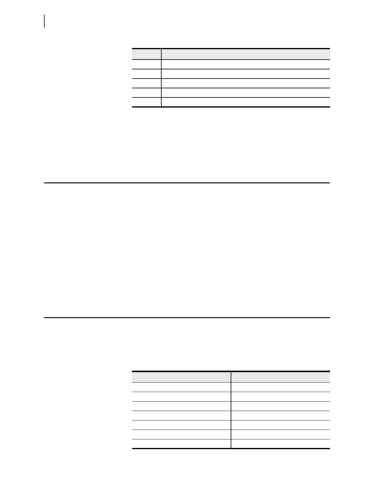
Ta b l e 8 .8 4 M IRRORED BITS Protocol Default Settings
Setting Default Value
MBANA1 LIAFM
MBANA2 LIBFM
MBANA3 LICFM
MBANA4 VAFM
MBANA5 VBFM
MBANA6 VCFM
MBANA7 VABRMS