5.18
SEL-421 Relay Instruction Manual Date Code 20171021
Protection Functions
Undervoltage Supervision Logic
Generally, settings VF01, VF02, VF03 correlate to VA, VB, and VC.
Equation 5.2 shows the relationship between the peak amplitude of Valpha and
the root-mean-square (RMS) value of the system voltage phasors for three-phase
voltage inputs.
NOTE: The relay uses the alpha
component voltage to track the
system frequency. To ensure the relay
uses the same voltage for frequency
tracking and frequency elements
undervoltage supervision, the
operating quantity in
Figure 5.13
was
changed from the positive-sequence
voltage to the alpha component
voltage. This change affects firmware
versions R310 and higher and may
require a revision of the 81UVSP
setting.
Equation 5.2
where VRMS is the root-mean-square value of the voltage phasor.
Relay Word bit 27B81 asserts if Valpha falls below the 81UVSP setting value for
longer than a cycle.
Calculate the 81UVSP Setting Value
Because the relay accepts voltage input from the potential transformers (PTs) in
any combination, Valpha can have different values, depending on the voltage
inputs. In general, the following examples use the average (60 percent) of the
50 to 70 percent undervoltage range that IEEE C37.117 Guide recommends.
Also, the calculations are based on an RMS phase-to-neutral value of 67 V for
the PT inputs, although the 81UVSP setting is a peak value and not an RMS
value.
Case 1: Three-Phase PT Inputs
In this case, VF01 = VA, VF02 = VB, and VF03 = VC (with default settings).
Use Equation 5.2 to calculate the nominal value of Valpha as follows:
Equation 5.3
Equation 5.4
Set 81UVSP to 60 percent of this value:
Equation 5.5
Equation 5.6
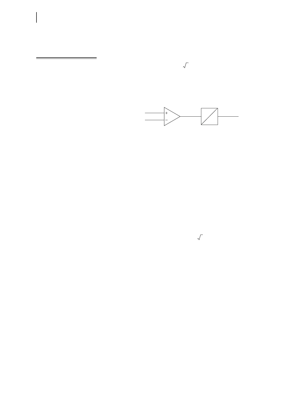
Figure 5.13 Undervoltage Supervision Logic
1.0 cyc
0.0
|Valpha|
81UVSP
27B81