4.9
Date Code 20171021 Instruction Manual SEL-421 Relay
Front-Panel Operations
Target L EDs
Target LEDs
The SEL-421 gives you at-a-glance confirmation of relay conditions via opera-
tion and target LEDs. These LEDs are located in the middle of the relay front
panel. The SEL-421 provides either 16 or 24 LEDs depending on ordering
option.
Section 4: Front-Panel Operations in the SEL-400 Series Relays Instruction
Manual describes the general operation and configuration of these LEDs. In the
SEL-421, targets latch when a trip occurs. For a concise listing of the default pro-
gramming on the front-panel LEDs, see Front-Panel Settings on page 8.35.
Use the slide-in labels to mark the LEDs with custom names. Included on the
SEL-421 Product Literature CD are Customer Label Templates to print labels for
the slide-in label carrier.
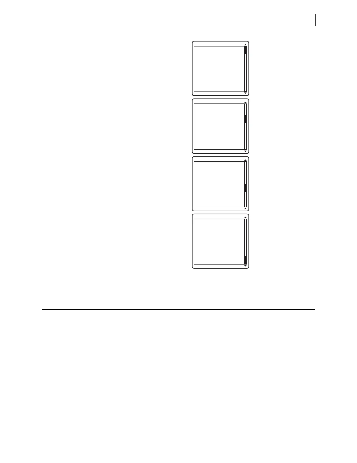
Figure 4.8 VIEW CONFIGURATION Sample Screens
FID=SEL-421-5-R101-
V0-Z012012-
D20100130
PART NUMBER: 0451541
5XC0X4H60X0XXX
S/N=201001001
SELBOOT:
BFID=SLBT-4XX-
R205-V0-Z001002-
D20100130
CHECKSUM: D97F
CONFIGURATION INFO
FIBER PORT:
NOT INSTALLED
INTERFACE BOARDS:
BOARD 1: 8 INPUTS
15 OUTPUTS
BOARD 2:NOT
INSTALLED
EXTENDED FEATURES:
DNP ACTIVE
CONFIGURATION INFO
MAINBOARD:
CODE FLASH: 4 MB
DATA FLASH: 8 MB
RAM: 3 MB
EEPROM: 32 KB
ANALOG INPUTS:
W: CURRENTS: 5 A
X: CURRENTS: 5 A
Y: VOLTAGE: 67 V
Z: VOLTAGE: 67 V
CONFIGURATION INFO
IF THE CONFIGURATION
IS NOT WHAT YOU
EXPECTED, CONTACT
SEL FOR ASSISTANCE.
CONFIGURATION INFO