16.31
Date Code 20171006 Instruction Manual SEL-400 Series Relays
DNP3 Communication
DNP3 LAN/WAN Application Example
DNP3 LAN/WAN Application Example
Application
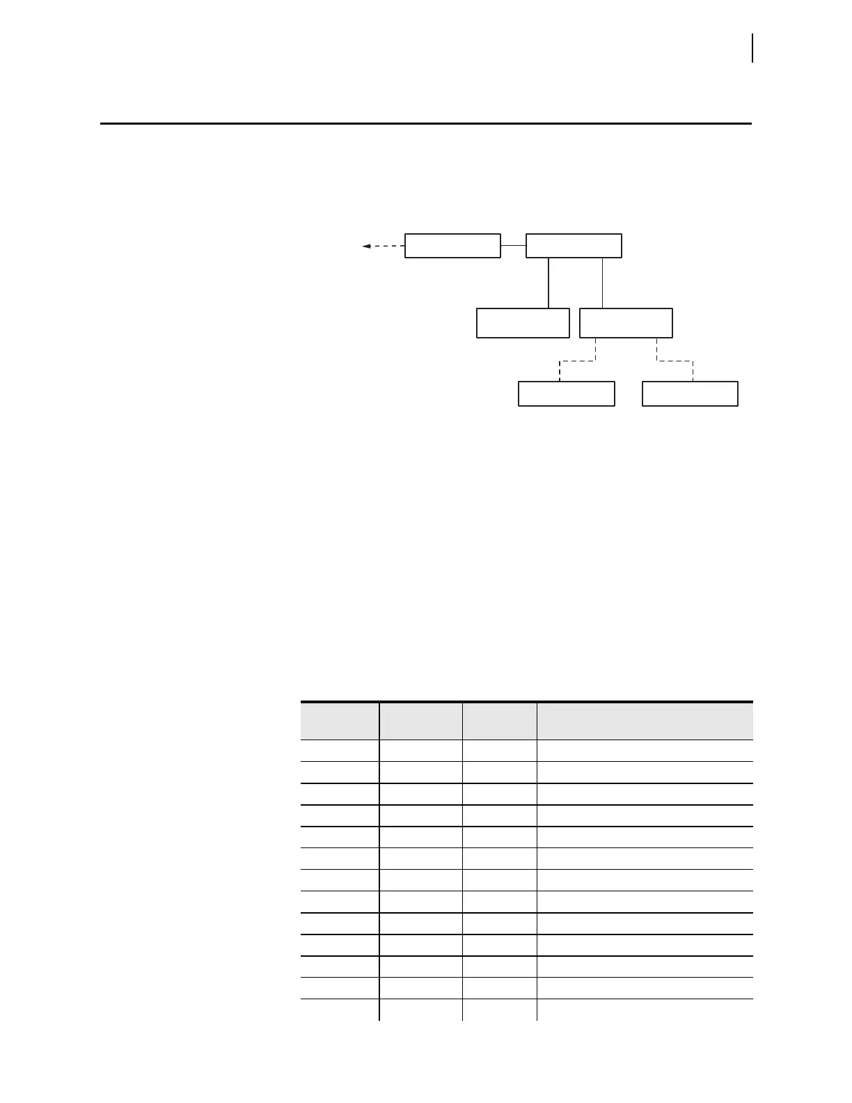
This example uses an SEL-487E connected to an RTU over an Ethernet (TCP)
network. The RTU collects basic metering information from the relay. The net-
work for this example is shown in Figure 16.8.
The polling method employed by the RTU DNP3 master is polled report-by-
exception, so it normally only does event polls. Once every 25 event polls, the
master polls for Class 0 data (status of all points). This polling method allows the
master to collect data efficiently from the IEDs by only polling and receiving data
that has changed.
The RTU, which will act as the DNP3 master to the SEL-487E outstation, has an
IP address of 192.9.0.3 and a DNP3 address of 12. The SEL-487E should be
assigned an IP address of 192.9.0.2, default router of 192.9.0.1, and DNP3
address of 101.
All event data (analog, binary, counter) should be assigned to CLASS 1. All
Binary Inputs should have SOE-quality time stamps.
The desired DNP3 data map is shown in Table 16.13.
Figure 16.8 DNP3 LAN/WAN Application Example Ethernet Network
Table 16.13 DNP3 Application Example Data Map (Sheet 1 of 2)
Label Object
Custom Map
Index
Description
EN 1, 2 0 Relay enabled
TRIPLED 1, 2 1 Circuit Breaker tripped
IN101 1, 2 2 Relay Discrete Input 1
IN102 1, 2 3 Relay Discrete Input 2
IN103 1, 2 4 Relay Discrete Input 3
IN104 1, 2 5 Relay Discrete Input 4
SALARM 1, 2 6 Relay software alarm
HALARM 1, 2 7 Relay hardware alarm
TESTDB2 1, 2 8 Test mode enabled
RB01 10, 12 0 Remote Bit 1
RB02 10, 12 1 Remote Bit 2
RB03 10, 12 2 Remote Bit 3
RB04 10, 12 3 Remote Bit 4
RTU
SEL-487E
Non-DNP3 IED
To SCADA
Network Switch
...
SEL-2030
Non-DNP3 IED