5.11
Date Code 20171021 Instruction Manual SEL-421 Relay
Protection Functions
Current and Voltage Source Selection
ESS := Y, Other Applications
Set ESS to Y for applications that are not covered under the five default applica-
tions.
Tapped Line
Figure 5.9 illustrates a tapped EHV transmission overhead line. A power trans-
former is located at Substation T along the tapped line. An SEL-421 is located at
all three EHV terminals (Substations S, R, and T). The SEL-421 Relays operate
in a DCB (directional comparison blocking) trip scheme to provide high-speed
clearance for all faults internal to the tapped EHV transmission line. For a com-
plete explanation of this example, see 230 kV Tapped Transmission Line Applica-
tion Example on page 6.170.
Set NUMBK (Number of Breakers in Scheme) to 2 so you can program the auto-
reclosing function and synchronism-check elements to control both of the low-
side circuit breakers.
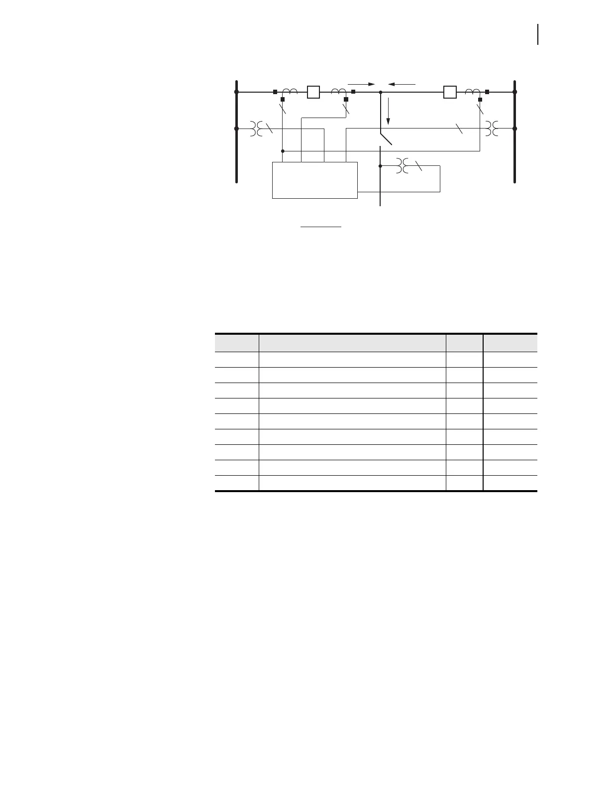
Figure 5.8 ESS := 4, Double Circuit Breaker Configuration
Table 5.9 ESS := 4, Current and Voltage Source Selection
Setting Prompt Entry Comments
NUMBK Number of Circuit Breakers in Scheme (1, 2) 2
LINEI Line Current Source (IW) IW Automatic
ALINEI Alternate Current Source (NA) NA Automatic
ALTI Alternate Current Source (SEL
OGIC Equation) NA Hidden
BK1I Breaker 1 Current Source (IX) IX Automatic
BK2I Breaker 2 Current Source (COMB) COMB Automatic
IPOL Polarizing Current (NA) NA Automatic
ALINEV Alternate Line Voltage Source (VZ, NA) NA
ALTV Alternate Voltage Source (SEL
OGIC Equation) NA Hidden
SEL-421 Relay
BUS 1 BUS 2
CB1 CB2
33
3
3
IW
IX
VAZ
VY
VBZ
1
1
Analog Input
IW+IX
IW
IX
VY
VAZ
VBZ
Function
CB2 protection
Line protection
CB1 protection
Line protection
Synchronism check Circuit Breaker 1
Synchronism check Circuit Breaker 2
I
CB1
I
CB2
I
LINE