5.46
SEL-421 Relay Instruction Manual Date Code 20171021
Protection Functions
Directionality
Directionality
Zone 1 and Zone 2 distance element directions are fixed in the forward direction.
You can select the other distance protection zones (Zone 3, Zone 4, and Zone 5)
independently as forward-looking (F), or reverse-looking (R) with settings DIR3,
DIR4, and DIR5.
Figure 5.27 32P, Phase Directional Element Logic Diagram
All Phase-to-Phase
Distance Elements Forward
All Phase-to-Phase
Distance Elements Reverse
ZLOAD
VPOLV
ILOP
F32Q
F32P
(Forward)
R32P
(Reverse)
R32Q
Relay
Word
Bit
Relay
Word
Bit
Relay
Word
Bits
Relay
Word
Bit
Relay
Word
Bit
Setting
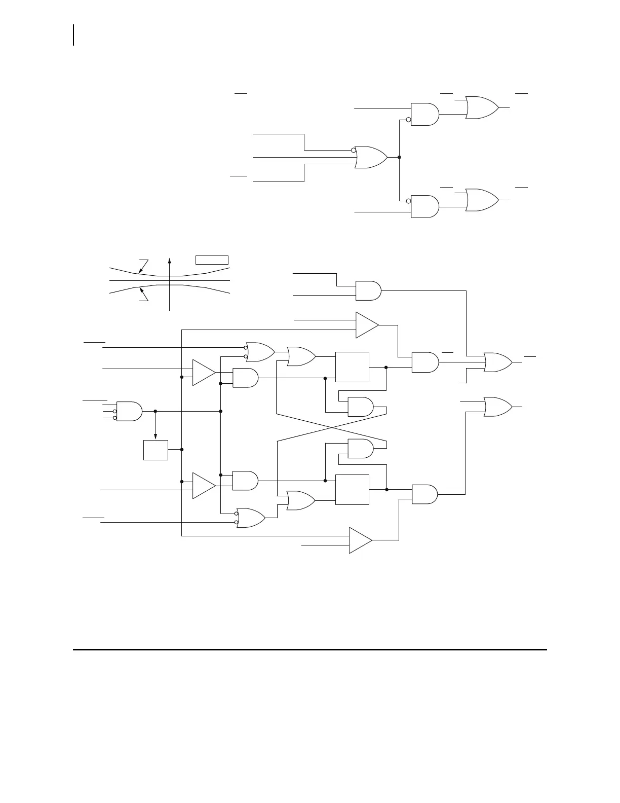
The stability counter can add as much as a 0.5 cycle delay. This prevents the logic from toggling between forward and
reverse declarations and gives other protection elements that rely on the directional decision time to operate.
Figure 5.28 32Q, Negative-Sequence Directional Element Logic Diagram
Relay
Word
Bits
Enable
Z2FTH
Z2RTH
Directional Element Characteristic
Clear
Assert
Forward
Stability
Counter
—
+
—
+
—
+
—
+
Clear
Assert
50QF
Z2F
(setting)
32QE
SPO
ILOP
z2
Z2R
(setting)
50QR
Reverse
Stability
Counter
F32Q
Relay
Word
Bits
32QF
32QR
HSDQF
HSDQR
R32Q
ELOP = Y
(setting)
LOP
(Relay Word Bit)
Z2FTH
Relay
Word Bit
Relay
Word Bits
Relay
Word Bit
Z2RTH
Z2 PLANE
R2
X2