3.12
SEL-421 Relay Instruction Manual Date Code 20171021
Testing
Checking Relay Operation
Step 4. Connect a test source to the relay.
a. Set the current output of a test source to zero output level.
b. Connect a single-phase current output of the test source to the
IAW analog input (see Figure 3.5 and Secondary Circuits on
page 2.5).
Step 5. Increase the current source to produce a current magnitude greater
than 1.00 A secondary in the relay.
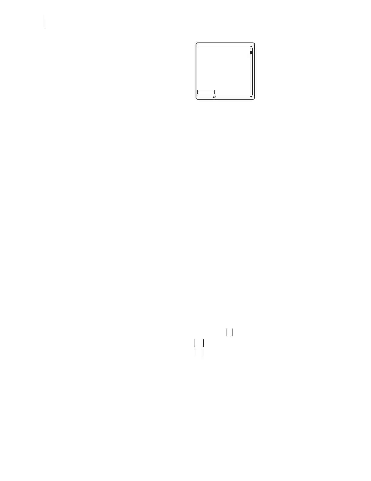
You will see that the 50Q1 element state changes on the LCD screen
from 50Q1 = 0 to 50Q1 = 1.
Negative-Sequence Directional Element for Phase Faults
The SEL-421 features a phase directional element (represented by Relay Word
bits F32P/R32P) to supervise the phase-distance elements and to control phase
directional elements. The negative-sequence directional element, F32Q/R32Q, is
a part of the phase directional element, F32P/R32P. Whenever the negative-
sequence directional element asserts, the phase directional element asserts.
The relay also contains a ground directional element, F32G/R32G, for directional
control of the ground-distance elements and ground overcurrent elements. For
more information on directional elements, see Ground Directional Element on
page 5.33, and Section 6: Protection Applications Examples.
The SEL-421 calculates the negative-sequence impedance Z2 from the magni-
tudes and angles of the negative-sequence voltage and current. Equation 3.1
defines this function (the ‘c’ in Z2c indicates “calculated”).
Equation 3.1
Figure 3.10 RELAY ELEMENTS Screen Containing Element 50Q1
PRESS to search
RELAY ELEMENTS
SEARCH
ROW 26 ROW 27
67Q4
=0 * =0
67Q3
=0 * =0
67Q2 =0 * =0
67Q1 =0 * =0
50Q4 =0 67Q4T =0
50Q3 =0 67Q3T =0
50Q2 =0 67Q2T =0
50Q1 =0 67Q1T =0
where:
V2 = the negative-sequence voltage
I2 = the negative-sequence current
Z1ANG = the positive-sequence line impedance angle
Re = the real part of the term in brackets, for example, (Re[A + jB] = A)
* = the complex conjugate of the expression in parentheses,
(A + jB)* = (A – jB)
Z2c
Re V
2
1 Z1ANG I
2
I
2
2
------------------------------------------------------------------------=
V
2
I
2
--------- V
2
Z1ANG I
2
––cos=