5.159
Date Code 20171021 Instruction Manual SEL-421 Relay
Protection Functions
Synchronism Check
noticeable voltage angle difference across the system (it is not simply zero
degrees). The corresponding angular separation results from load flow and the
impedance of the parallel system.
You must consider this angle difference when setting the synchronism-check ele-
ment for a paralleled system. For example, if the expected angle because of load
flow is 10 degrees, do not set the voltage angle difference setting to less than
15–20 degrees nominal. A paralleled system does not imply a zero degree voltage
angle difference at every measuring point.
Single-Phase Voltage Inputs
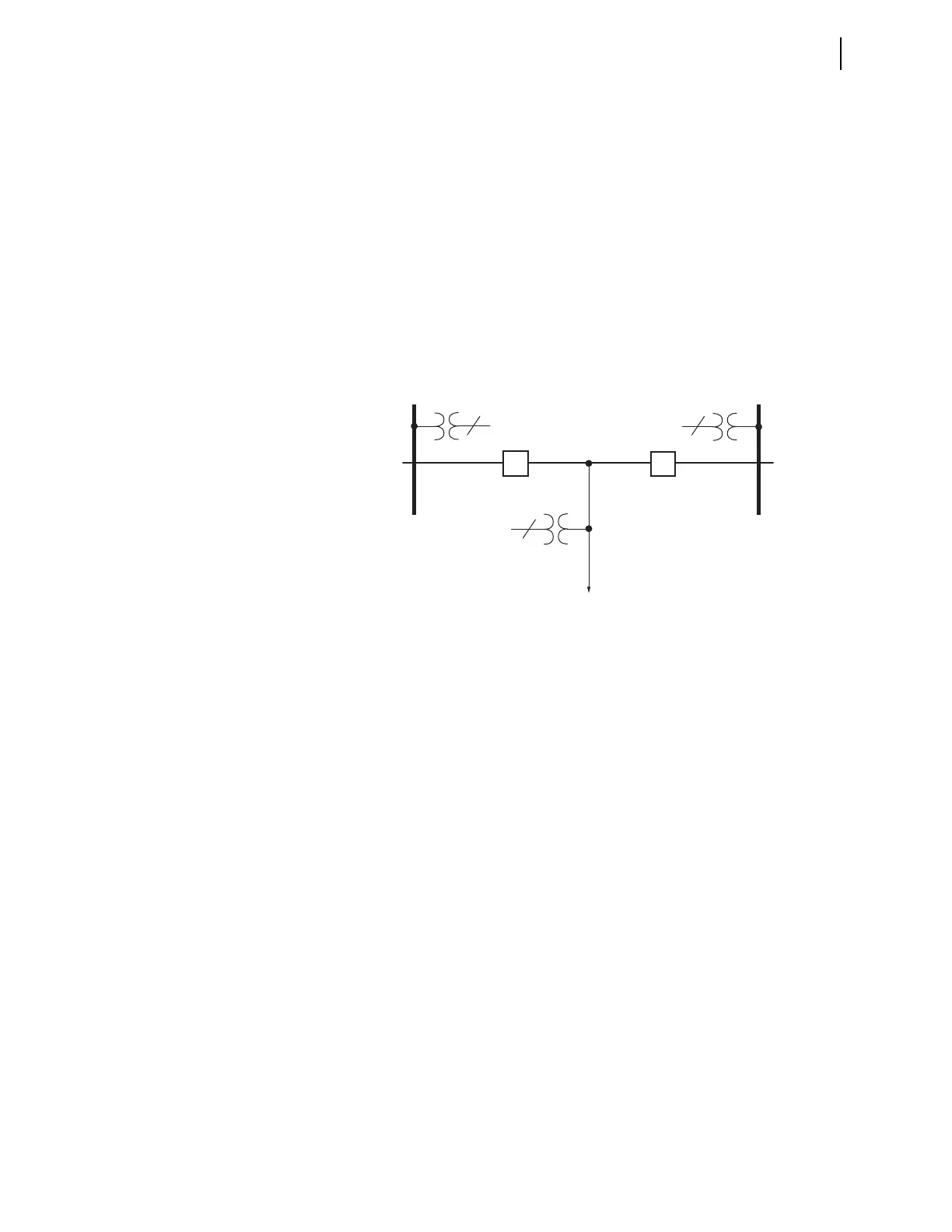
Figure 5.119 shows single-phase voltage transformers (1 PT) on Bus 1 and
Bus 2. Use these single-phase voltage sources to perform a synchronism check
across the two circuit breakers.
Synchronism check occurs on a single-phase voltage basis—see the single-phase
potential transformers (1 PT) shown on each bus in Figure 5.119. The assump-
tion is that if the monitored single-phase voltage inputs are in phase (within a set-
table voltage angle difference), and they meet the criteria of being healthy (within
a settable voltage magnitude window) and/or the voltage difference is less than a
set limit, the other phase-to-neutral voltages are likewise in phase and share the
same voltage magnitude relationship. The line voltage source is three-phase, but
you only need a single-phase bus voltage to perform a synchronism check across
the corresponding circuit breaker. The relay uses the three-phase voltage from the
line for other functions such as distance protection and metering.
Setting E25BK
n
:= Y
If E25BKn is set to Y, where n = 1 or 2, the synchronizing logic verifies that both
the reference voltage and synchronizing voltage are healthy (within a settable
voltage magnitude window) before enabling the synchronism-check logic.
Setting E25BK
n
:= Y1
If E25BKn is set to Y1, where n = 1 or 2, the synchronizing logic verifies that the
difference voltage between the reference and synchronizing voltages is less than
the 25VDIF setting before enabling the synchronism-check logic.
Figure 5.119 Synchronism-Check Voltages for Two Circuit Breakers
Bus 2
Bus 1
Line
BK2
BK1
1
3
1
. . . . . .
. . .


 To Next Page