6.125
Date Code 20171021 Instruction Manual SEL-421 Relay
Protection Applications Examples
Out-of-Step Logic Application Examples
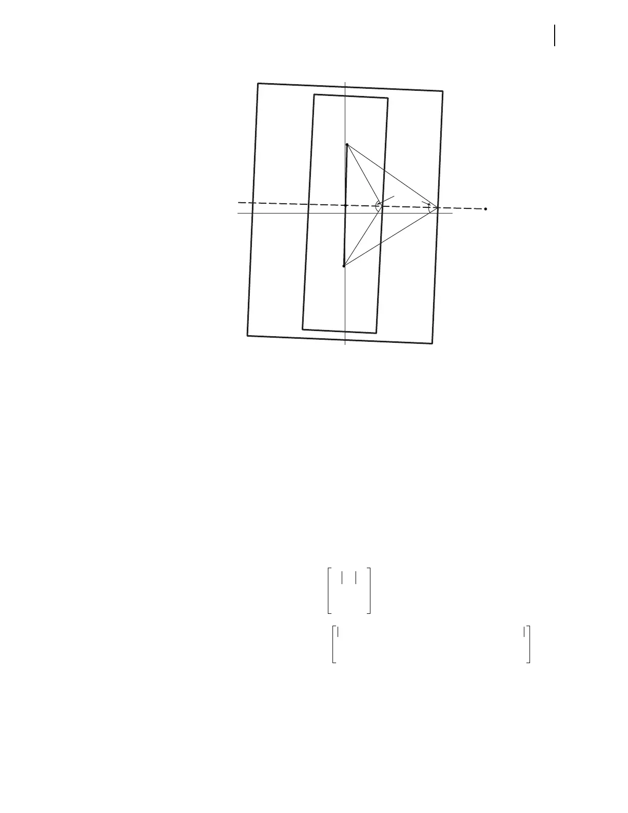
Use Equation 6.76 through Equation 6.79 to calculate the OSBD setting. These
equations are derived from the impedance trajectory shown in Figure 6.31. Line
section AB is the transfer impedance, Z
T
. The horizontal dashed line represents
the trajectory of the power swing perpendicular to line section AB. The trajectory
passes through the midpoint of line section AB.
Equation 6.76
Equation 6.77
Figure 6.31 Swing Trajectory to Determine the OSBD Setting
where:
Z
T
= transfer impedance
Z1
S
= positive-sequence source impedance
Z1
L1
= positive-sequence impedance for Line 1
Z1
R
= positive-sequence remote impedance
B
A
Minimum Load
Impedance
Z
1
Trajectory
R1
X1
O
Ang_R6
Zone 6
Zone 7
Ang_R7
Ang_R6 2
Z
T
2
---------
R1R6
-------------------
atan• =
2
8.8 88 8.00 87.6 3.52 88++
2
--------------------------------------------------------------------------------------------------------------
5.77
--------------------------------------------------------------------------------------------------------------
atan•
=
120.9=