6.168
SEL-421 Relay Instruction Manual Date Code 20171021
Protection Applications Examples
Circuit Breaker Failure Application Examples
OUT208 := RTB2.
OUT209 := RTC2.
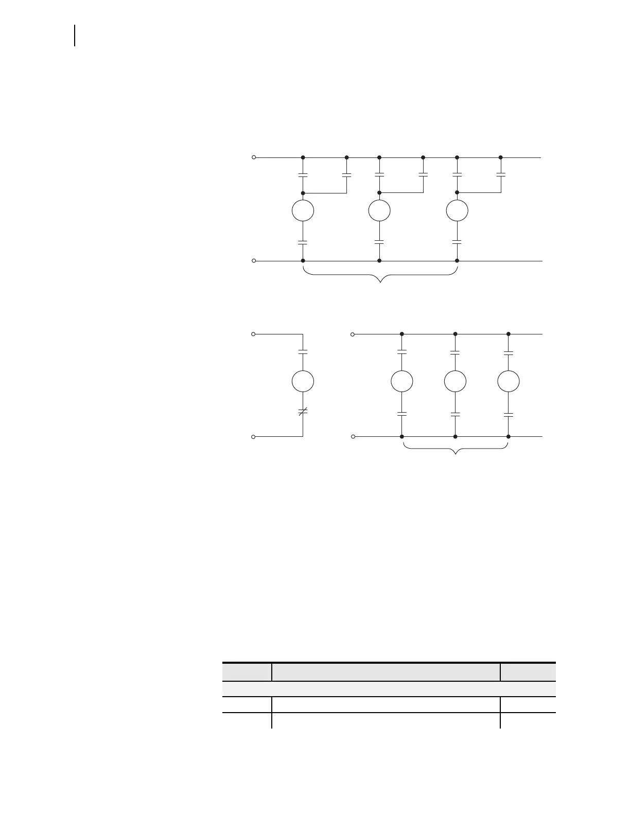
Figure 6.49 illustrates the corresponding dc connections for Circuit Breaker
BK1. Circuit Breaker BK2 connections are similar.
Example Completed
This completes the application example that describes setting the SEL-421 for
Scheme 2 circuit breaker failure protection. Analyze your particular power sys-
tem to determine the appropriate settings for your application.
Relay Settings
Figure 6.44 lists all protective relay settings applied for this example. These set-
tings are for Circuit Breaker BK1; settings for Circuit Breaker BK2 are similar
unless otherwise noted.
Figure 6.49 Circuit Breaker BK1 DC Connections (Two Trip Coils)
86-1
86-1
86-1
BFTRIP1
(OUT107)
DC1 (—)
DC2 (—)
DC2 (+)
DC1 (+)
TCA-1
TPA1
(OUT101)
BK1 TRIP COILS #1
BK1 TRIP COILS #2
TCA-2
52AA1
RTA1
(OUT204)
TCB-2
52AB1
RTB1
(OUT205)
TCC-2
52AC1
RTC1
(OUT206)
DC3 (-)
DC3 (+)
52AA1
86-1
TCB-1
TPB1
(OUT102)
52AB1
86-1
TCC-1
TPC1
(OUT103)
52AC1
Table 6.44 Settings for Circuit Breaker Failure Example 2 (Sheet 1 of 2)
Setting Prompt Entry
Relay Configuration (Group)
EBFL1 Breaker 1 Failure Logic (N, 1, 2, Y1, Y2) 2
EBFL2 Breaker 2 Failure Logic (N, 1, 2, Y1, Y2) 2