2.22
SEL-421 Relay Instruction Manual Date Code 20171021
Installation
Jumpers
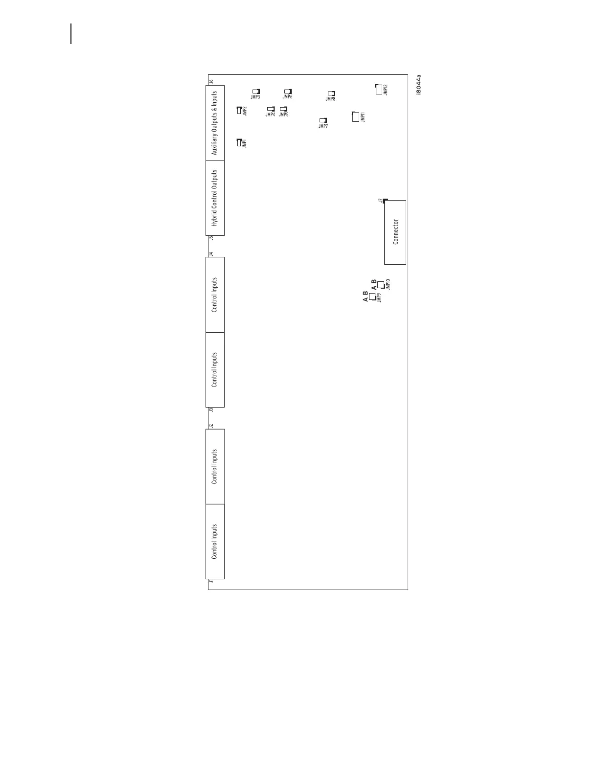
To confirm the positions of your I/O board jumpers, remove the front panel and
visually inspect the jumper placements. Table 2 .7 lists the four jumper positions
for I/O interface boards. Refer to Figure 2.20 for the locations of these jumpers.
The I/O board control address has a hundreds-series prefix attached to the control
inputs and control outputs for that particular I/O board chassis slot. A 4U chassis
has a 200-addresses slot for inputs IN201, IN202, etc., and outputs OUT201,
OUT202, etc. A 5U chassis has a 200-addresses slot and a 300-addresses slot.
Figure 2.21 Major Component Locations on the SEL-421 INT3 I/O Board
Rear of Relay