5.34
SEL-421 Relay Instruction Manual Date Code 20171021
Protection Functions
Ground Directional Element
The negative-sequence voltage polarized directional element 32QG listed in
Table 5.31 supervises the ground-distance elements and residual ground direc-
tional overcurrent elements. The negative-sequence voltage polarized directional
element 32Q illustrated in Figure 5.28 only supervises the phase-distance ele-
ments.
The relay internal logic selects the best choice for directional supervision accord-
ing to prevailing power system conditions during the ground fault. The logic
determines the best choice for the ground directional element (32G) from among
the negative-sequence voltage-polarized directional element (32QG), zero-
sequence voltage-polarized directional element (32V), or the zero-sequence cur-
rent-polarized directional element (32I). The ground directional element also
supervises the quadrilateral ground-distance elements.
During the single-pole open condition (SPO is a logical 1), the relay supervises
the ground directional element with an open-pole directional element. The pur-
pose of this directional element is to ensure secure operation of the distance ele-
ments during the single-pole open condition. The operation of the single-pole
open directional element is indicated by the 32SPOF and the 32SPOR Relay
Word bits.
As the single-pole open directional element may operate because of unbalance
currents generated during the single-pole open condition, it is recommended that
ground and negative-sequence overcurrent elements that are used for single-pole
tripping be supervised by the single-pole open condition. To supervise overcur-
rent elements during the single-pole open condition, set the element torque con-
trol equation (67GnTC or 67QnTC, where n equals 1–4) equal to NOT SPO.
Settings
Table 5.32 lists the relay settings corresponding to the ground directional ele-
ment.
If you set E32 to AUTO, the relay automatically calculates the settings shown in
Table 5.33.
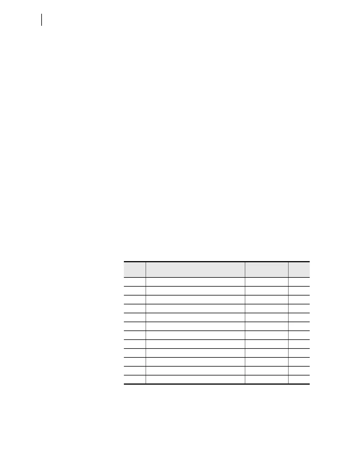
Table 5.32 Ground Directional Element Settings
Setting Prompt Range
Default
(5 A)
E32 Directional Control Y, AUTO, AUTO2 AUTO2
ORDER Ground Directional Element Priority combine Q, V, I QV
50FP Forward Directional Overcurrent Pickup (A) (0.05–1) • I
NOM
0.50
50RP Reverse Directional Overcurrent Pickup (A) (0.05–1) • I
NOM
0.25
Z2F Forward Directional Z2 Threshold () ±320/I
NOM
–0.30
Z2R Reverse Directional Z2 Threshold () ±320/I
NOM
0.30
a2 Positive-Sequence Restraint Factor, I2/I1 0.02–0.5 0.10
k2 Zero-Sequence Restraint Factor, I2/I0 0.1–1.2 0.20
Z0F Forward Directional Z0 Threshold () ±320/I
NOM
–0.30
Z0R Reverse Directional Z2 Threshold () ±320/I
NOM
0.30
a0 Positive-Sequence Restraint Factor, I0/I1 0.02–0.5 0.10
E32IV Zero-Sequence Voltage Current Enable SEL
OGIC Equation 1