6.105
Date Code 20171021 Instruction Manual SEL-421 Relay
Protection Applications Examples
EHV Parallel 230 kV Underground Cables Example
Disable Level 1 negative-sequence overcurrent element. This application does
not use 50Q1.
50Q1P := OFF. Level 1 Pickup (OFF, 0.25–100 A secondary)
The Level 2 negative-sequence directional overcurrent element (67Q2) provides
communications-assisted tripping for internal unbalanced faults. This element
detects unbalanced faults in the forward direction and trips via the communica-
tions channel. The 50Q2P setting is the pickup for the directional overcurrent ele-
ment 67Q2. Apply a setting equal to the default for the pickup of 32QG
(Negative-Sequence Voltage Polarized Directional Element), which is 50FP (For-
ward Supervisory Overcurrent Pickup)
50Q2P = 50FP = 0.12 • I
NOM
= 0.12 • 5 A = 0.6 A
50Q2P := 0.60. Level 2 Pickup (OFF, 0.25–100 A secondary)
The Level 3 negative-sequence directional overcurrent element (67Q3) provides
current reversal guard during unbalanced faults on the parallel cable to prevent
unwanted tripping. The 50Q3P setting is the pickup for directional overcurrent
element 67Q3. Set the pickup of Level 3 negative-sequence overcurrent element
equal to the default for the pickup of 32QG (Negative-Sequence Voltage Polar-
ized Directional Element), which is 50RP (Reverse Supervisory Overcurrent
Pickup). The reverse-looking element is 150 percent more sensitive than the for-
ward-looking element.
50Q3P = 50RP = 0.08 • I
NOM
= 0.08 • 5 A = 0.4 A
50Q3P := 0.40. Level 3 Pickup (OFF, 0.25–100 A secondary)
Negative-Sequence Overcurrent Pickup Coordination Check
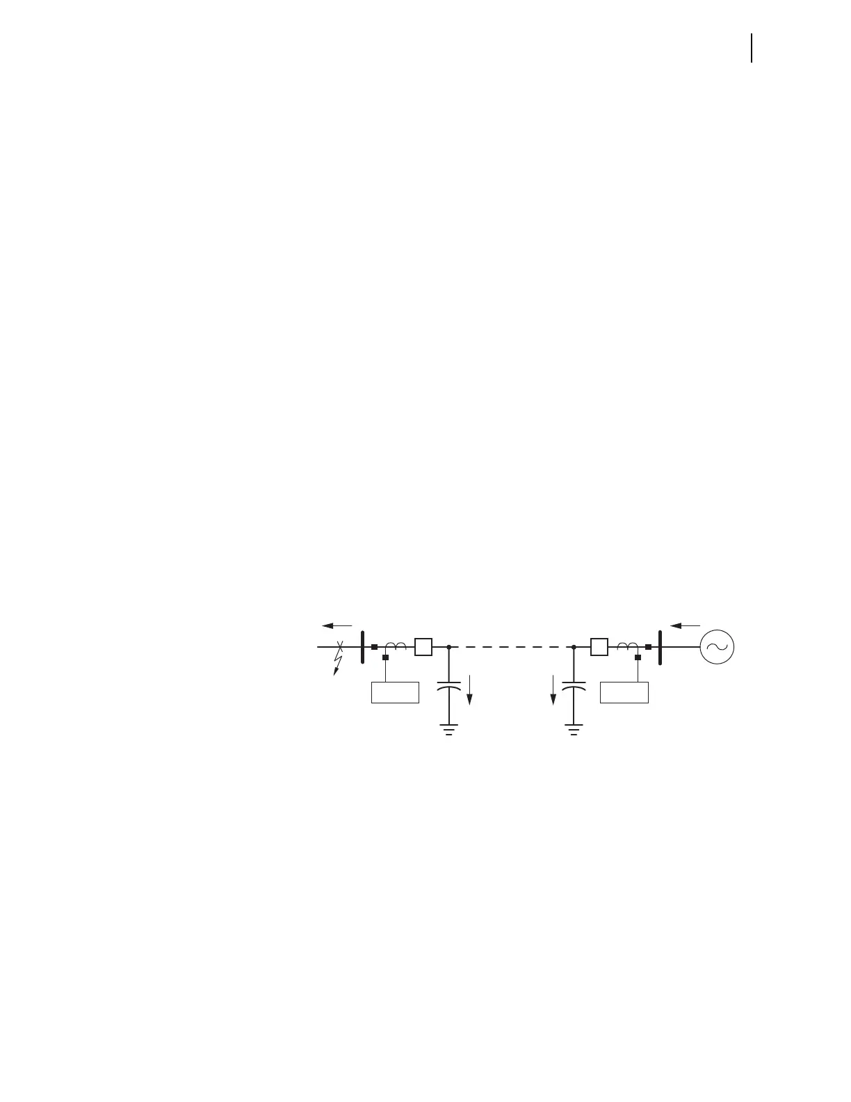
Figure 6.26 illustrates why you need to check the sensitivity of the forward
(50Q2P) and reverse (50Q3P) negative-sequence overcurrent pickup settings.
The shunt capacitance of the 230 kV cable causes the SEL-421 at Station S to
measure less negative-sequence fault current for a reverse out-of-section ground
fault than at Station R.
Equation 6.65
Figure 6.26 Negative-Sequence Fault Current Distribution-External Ground Fault
where:
I
2R
= negative-sequence fault current supplied from Source R
I
2S
= negative-sequence fault current flowing through the line termi-
nal at Station S
I
2CR
= negative-sequence shunt current at Station R
I
2CS
= negative-sequence shunt current at Station S