2.26
SEL-421 Relay Instruction Manual Date Code 20171021
Installation
Connection
Rear-Panel Layout
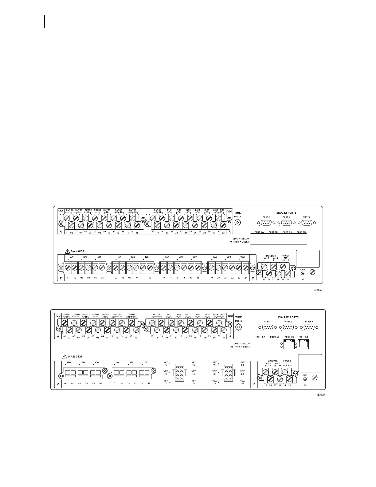
Figure 2.23 through Figure 2.32 show available SEL-421 rear panels.
All relay versions have screw-terminal connectors for I/O, power, and battery
monitor. You can order the relay with fixed terminal blocks for the CT and PT
connections, or you can order SEL Connectorized rear-panel configurations that
feature plug-in/plug-out PT connectors and shorting CT connectors for relay ana-
log inputs. Figure 2.24 shows the Connectorized 3U horizontal configuration of
the SEL-421.
The screw-terminal connections for the INT1 (or INT2) and the INT6 (or INT7)
I/O interface boards are the same. The INT5 (or INT8) I/O interface board has
control output terminals grouped in threes, with the fourth terminal as a blank
additional separator (terminals 4, 8, 12, 16, 20, 24, 28, and 32). The INT3, INT4,
and INT5 (or INT8) I/O interface boards both contain high-speed, high-current
interrupting control outputs, but use a different terminal layout—see Control
Outputs on page 2.8 for details.
For more information on the main board control inputs and control outputs, see
Main Board I/O on page 2.11. For more information on the I/O interface board
control inputs and control outputs, see I/O Interface Board Jumpers on
page 2.20.
Figure 2.23 3U Rear Panel, Main Board
Figure 2.24 3U Rear Panel, Main Board, Connectorized