4.18
SEL-421 Relay Instruction Manual Date Code 20171021
Front-Panel Operations
One-Line Diagrams
Predefined Bay Control One-Line Diagrams
Configurations
The following pages illustrate all of the predefined busbar and bay control con-
figurations in the SEL-421 defined by the (MIMIC settings). Select the bay
screen that exactly matches the bay configuration being controlled from the fol-
lowing figures.
➤ Figure 4.15–Figure 4.17: Main Bus and Auxiliary Bus one-line
diagram
➤ Figure 4.18–Figure 4.19: Bus 1, Bus 2, and Transfer Bus one-line
diagram
➤ Figure 4.20: Transfer Bay one-line diagram
➤ Figure 4.21: Tie Breaker Bay one-line diagram
➤ Figure 4.22–Figure 4.23: Main Bus and Transfer Bus one-line
diagram
➤ Figure 4.24–Figure 4.25: Main Bus one-line diagram
➤ Figure 4.26–Figure 4.30: Breaker-and-a-Half one-line diagram
➤ Figure 4.31–Figure 4.32: Ring Bus one-line diagram
➤ Figure 4.33–Figure 4.36: Double Bus Double Breaker one-line
diagram
➤ Figure 4.37: Source Transfer Bus one-line diagram
➤ Figure 4.38–Figure 4.39: Throw-Over Bus one-line diagram
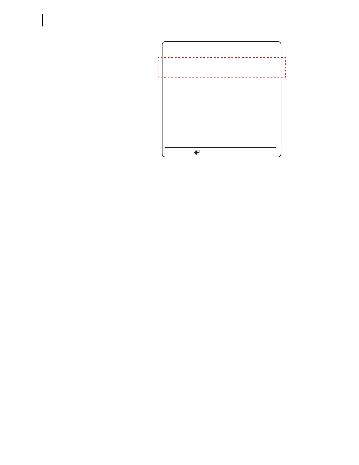
Figure 4.14 Pole Discrepancy
A B C
OPEN CLOSED OPEN
BREAKER 1
BREAKER 1 STATUS
TRIP BREAKER 1
CLOSE BREAKER 1
Press TO ACTIVATE