2.4
SEL-421 Relay Instruction Manual Date Code 20171021
Installation
Shared Configuration Attributes
Connector Types
Screw-Terminal Connectors—I/O and Monitor/Power
Connect to the relay I/O and Monitor/Power terminals on the rear panel through
screw-terminal connectors. You can remove the entire screw-terminal connector
from the back of the relay to disconnect relay I/O, dc battery monitor, and power
without removing each wire connection. The screw-terminal connectors are
keyed (see Figure 2.34), so you can replace the screw-terminal connector on the
rear panel only at the location from which you removed the screw-terminal con-
nector. In addition, the receptacle key prevents you from inverting the screw-ter-
minal connector, making removal and replacement easier.
Secondary Circuit Connectors
Fixed Terminal Blocks
Connect PT and CT inputs to the fixed terminal blocks in the bottom row of the
relay rear panel.
You cannot remove these terminal blocks from the relay rear panel. These termi-
nals offer a secure high-reliability connection for PT and CT secondaries.
Connectorized
The Connectorized SEL-421 features receptacles that accept plug-in/plug-out
connectors for terminating PT and CT inputs; this requires ordering a wiring har-
ness (SEL-WA0421) with mating plugs and wire leads. Figure 2.3 shows the
relay 3U chassis with Connectorized CT and PT analog inputs (see Connector-
ized on page 2.35 for more information).
Time-Domain Link (TiDL)
The TiDL SEL-421 features eight fiber-optic EtherCAT connections instead of
the standard CT and PT analog inputs (see TiDL Connections on page 2.38 for
more information).
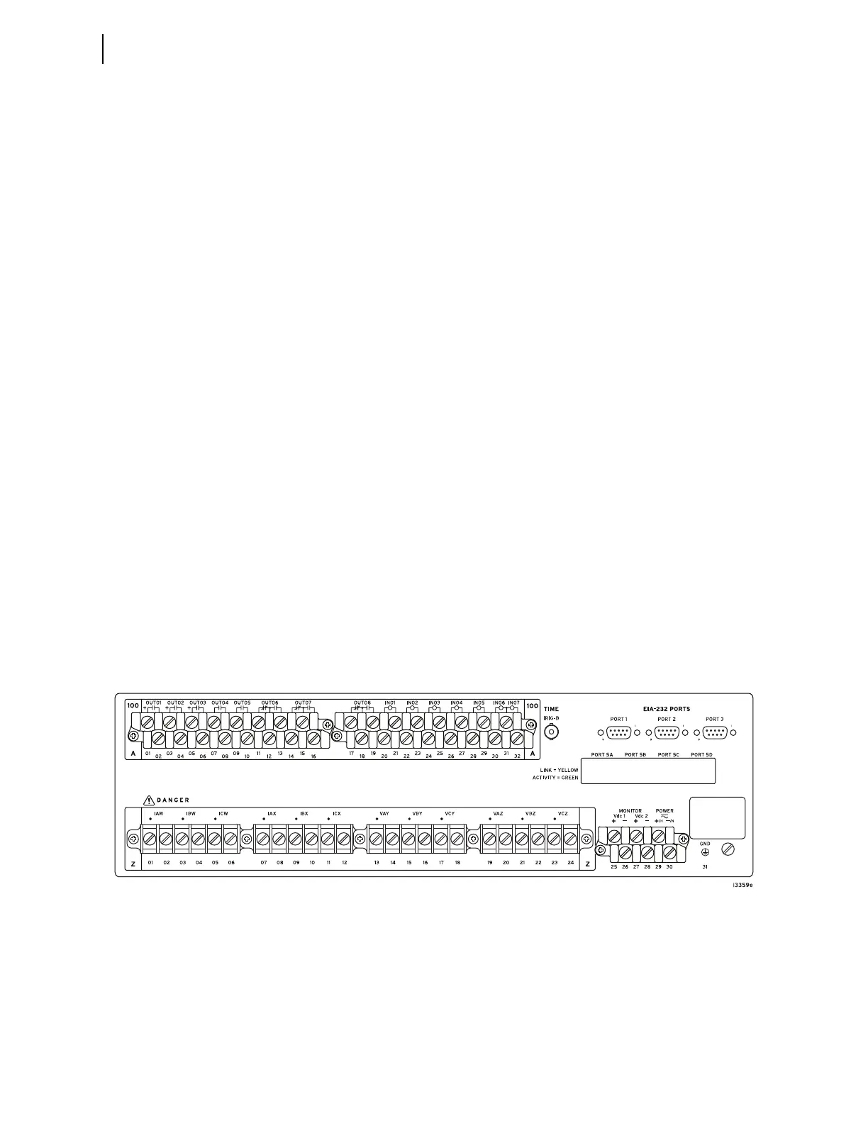
(In a vertical-mount relay, the right rear side is at the top.)
Figure 2.2 Rear 3U Template, Fixed Terminal Block Analog Inputs