5.166
SEL-421 Relay Instruction Manual Date Code 20171021
Protection Functions
Synchronism Check
Voltage Difference Checks (Applicable When E25BK
n
= Y1 or Y2)
For synchronism check to proceed for a given circuit breaker (BK1 or BK2)
when E25BKn = Y1 or Y2, the absolute value of the difference between the syn-
chronism-check reference voltage, V
P
, and the corresponding normalized syn-
chronism-check voltage source on the other side of the circuit breaker
(normalized voltage V
S1
for Circuit Breaker BK1 and normalized voltage V
S2
for
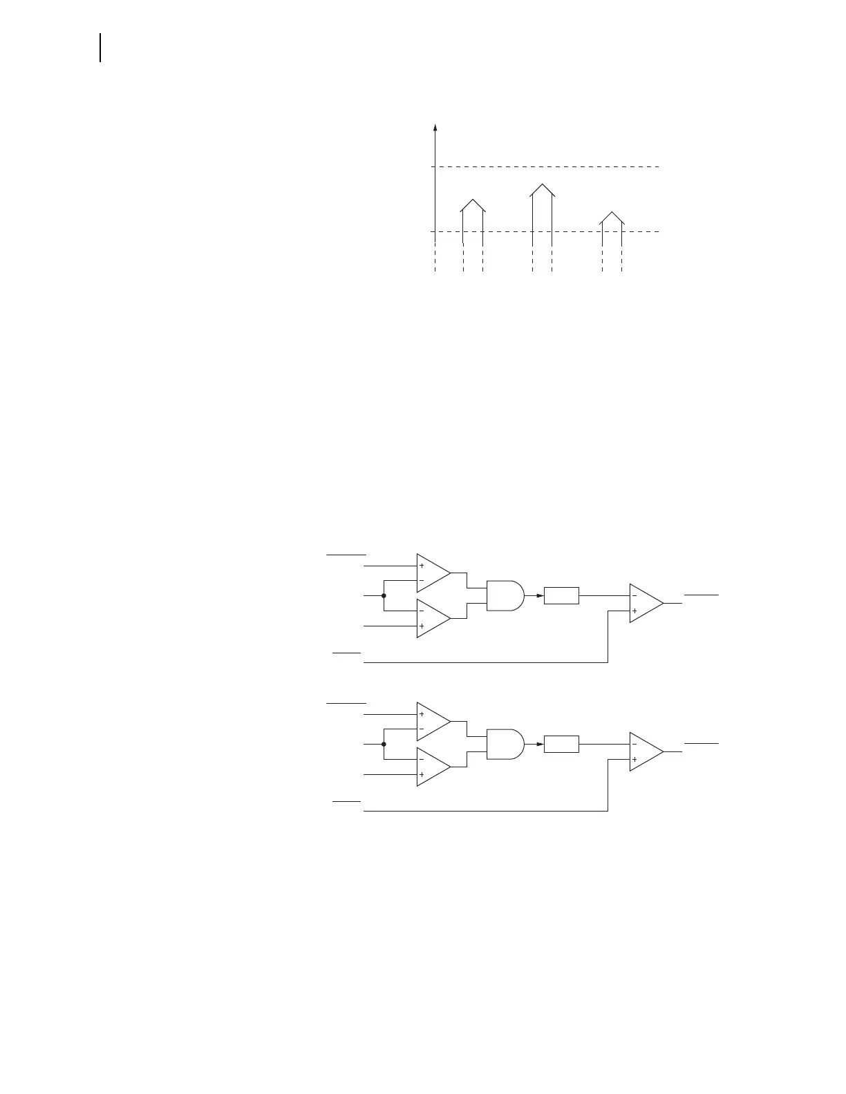
Circuit Breaker BK2) must be less than the 25VDIF setting (see Figure 5.126).
The logic includes a 5-volt secondary check to ensure the relay does not operate
on erroneous signals.
Block Synchronism Check
If the block synchronism check BSYNBKn SELOGIC control equation (where
n = 1 or 2 for Circuit Breaker BK1 or Circuit Breaker BK2, respectively) asserts,
synchronism check cannot proceed for the corresponding circuit breaker. Follow-
ing is an example for Circuit Breaker BK1:
BSYNBK1 := 52AA1 AND 52AB1 AND 52AC1. Block Synchronism Check—BK1
(SEL
OGIC Equation)
Figure 5.125 Healthy Voltage Window and Indication
V
S1
V
S2
25VL=60
25VH=73
59VS1 =
logical 1
59VP =
logical 1
59VS2 =
logical 1
Voltage
magnitude
(V
P
base)
Corresponding
Relay
Word Bits:
V
P
Figure 5.126 Synchronism-Check Voltage Difference Logic
Analog
Quantities
Setting
V
P
V
S1
5 Volts
25VDIF
Relay
Word Bit
59VDIF1
|V
P
–V
S1
|
Analog
Quantities
Setting
V
P
V
S2
5 Volts
25VDIF
Relay
Word Bit
59VDIF2
|V
P
–V
S2
|