2.14
SEL-421 Relay Instruction Manual Date Code 20171021
Installation
Plug-In Boards
The I/O interface boards carry jumpers that identify the board location (see
Jumpers on page 2.15).
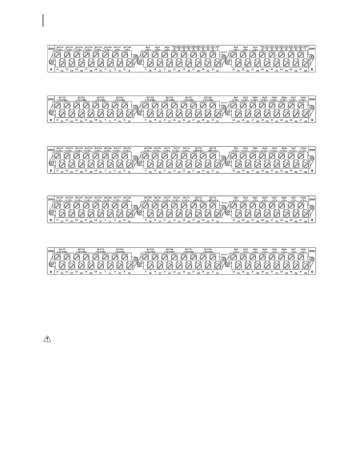
I/O Interface Board Inputs
The INT1, INT5, and INT6 I/O interface boards have eight independent control
inputs. All independent inputs are isolated from other inputs. These high-isola-
tion control inputs are direct coupled and hence polarity-sensitive. You cannot
damage these inputs with a reverse polarity connection; though, the relay will not
detect input changes with a reverse-polarity input.
The INT3 and INT4 I/O interface board has two groups of nine (9) common con-
tacts (18 total) and six (6) independent control inputs. The INT2, INT7, and INT8
I/O interface boards have eight independent control inputs. All independent
inputs are isolated from other inputs. These control inputs are optoisolated and
hence are not polarity sensitive, i.e., the relay will detect input changes with volt-
age applied at either polarity, or ac signals (when properly configured, see
Optoisolated on page 2.7).
Figure 2.13 INT4 I/O Interface Board
Figure 2.14 INT5 I/O Interface Board
Figure 2.15 INT6 I/O Interface Board
Figure 2.16 INT7 I/O Interface Board
Figure 2.17 INT8 I/O Interface Board
Substation battery systems that have
either a high resistance to ground
(greater than 10 k) or are
ungrounded when used in conjunction
with many direct-coupled inputs can
reflect a dc voltage offset between
battery rails. Similar conditions can
exist for battery monitoring systems
that have high-resistance balancing
circuits or floating grounds. For these
applications, SEL provides optional
ground-isolated (optoisolated) con-
tact inputs. In addition, SEL has pub-
lished an application advisory on this
issue. Contact the factory for more
information.