5.149
Date Code 20171021 Instruction Manual SEL-421 Relay
Protection Functions
Circuit Breaker Failure Protection
Failure to Interrupt Fault Current: Scheme Y2 (Setting EBFL = Y2)
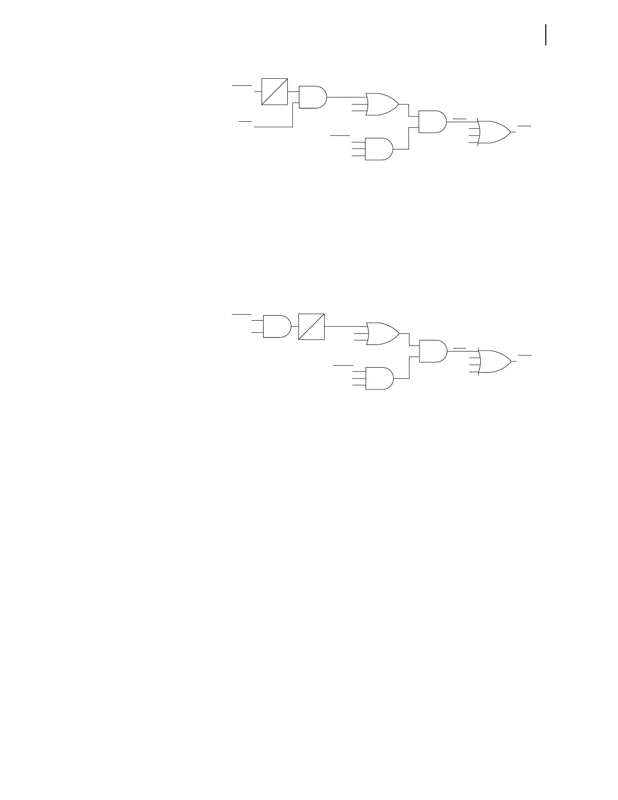
Three-Pole Circuit Breaker Failure Protection Logic
The logic shown in Figure 5.106 applies to three-pole breaker configurations.
Scheme Y2 is similar to Scheme 2, but the current check (50FA1) is now part of
the Breaker Failure initiate timer (BFPU1) in addition to the Breaker Failure ini-
tiate settings (BFI3P1 or BFIA1).
Failure to Interrupt Fault Current: Scheme 2 (Setting EBFL = 2)
Circuit Breaker Failure Protection Logic: Single-Phase Faults
The logic diagram shown in Figure 5.107 applies to single-pole tripping for one
or two circuit breakers (EBFL = 2). A-Phase is discussed; B-Phase and C-Phase
logic is similar. Use this logic when one pole of the circuit breaker fails following
a single-pole trip from the line-relaying scheme.
Fault current causes 50FA1 (Breaker 1 A-Phase Instantaneous Overcurrent Ele-
ment) to assert immediately following ground fault inception and just prior to the
assertion of Relay Word bit BFIA1 (Breaker 1 A-Phase Circuit Breaker Failure
Initiation). At circuit breaker failure initiation timer BFPU1 (Breaker 1 Circuit
Breaker Failure Time Delay on Pickup Timer) starts timing. Timer BFPU1 cas-
cades into timer SPBFPU1 (Breaker 1 Single-Pole Trip Breaker Failure Time
Delay on Pickup Timer). Therefore, use this second timer, SPBFPU1, to coordi-
nate circuit breaker failure operations for single-pole and three-pole trips.
If 50FA1 remains asserted when timer SPBFPU1 expires and neither of the two
Relay Word bits BFIB1 and BFIC1 is asserted, Relay Word bit FBFA1 (A-Phase
Breaker 1 Circuit Breaker Failure) asserts. Use FBFA1 in the circuit breaker fail-
ure tripping logic to cause a circuit breaker failure trip (see Circuit Breaker Fail-
ure Trip Logic on page 5.154). If the protected circuit breaker successfully opens,
50FA1 drops out before timer SPBFPU1 expires and Relay Word bit FBFA1 does
not assert.
Figure 5.105 Scheme 2 Three-Pole Circuit Breaker Failure Protection Logic
FBF1
BFIA1
50FA1
B-Phase
C-Phase
BFIA1
BFIB1
BFIC1
FBFC1
FBFB1
FBFA1
A-Phase
Relay
Word
Bit
Relay
Word
Bit
Relay
Word
Bits
SELOGIC
Settings
SELOGIC
Setting
BFPU1
0
2 of 3
Figure 5.106 Scheme Y2 Three-Pole Circuit Breaker Failure Logic
FBF1
BFIA1
50FA1
B-Phase
C-Phase
BFIA1
BFIB1
BFIC1
FBFC1
FBFB1
FBFA1
A-Phase
Relay
Word
Bit
Relay
Word
Bits
SELOGIC
Settings
SELOGIC
Setting
BFPU1
0
2 of 3