5.67
Date Code 20171021 Instruction Manual SEL-421 Relay
Protection Functions
Out-of-Step Logic (Zero Settings)
Figure 5.49 shows the I0/I2 angular relationship during a single pole-open condi-
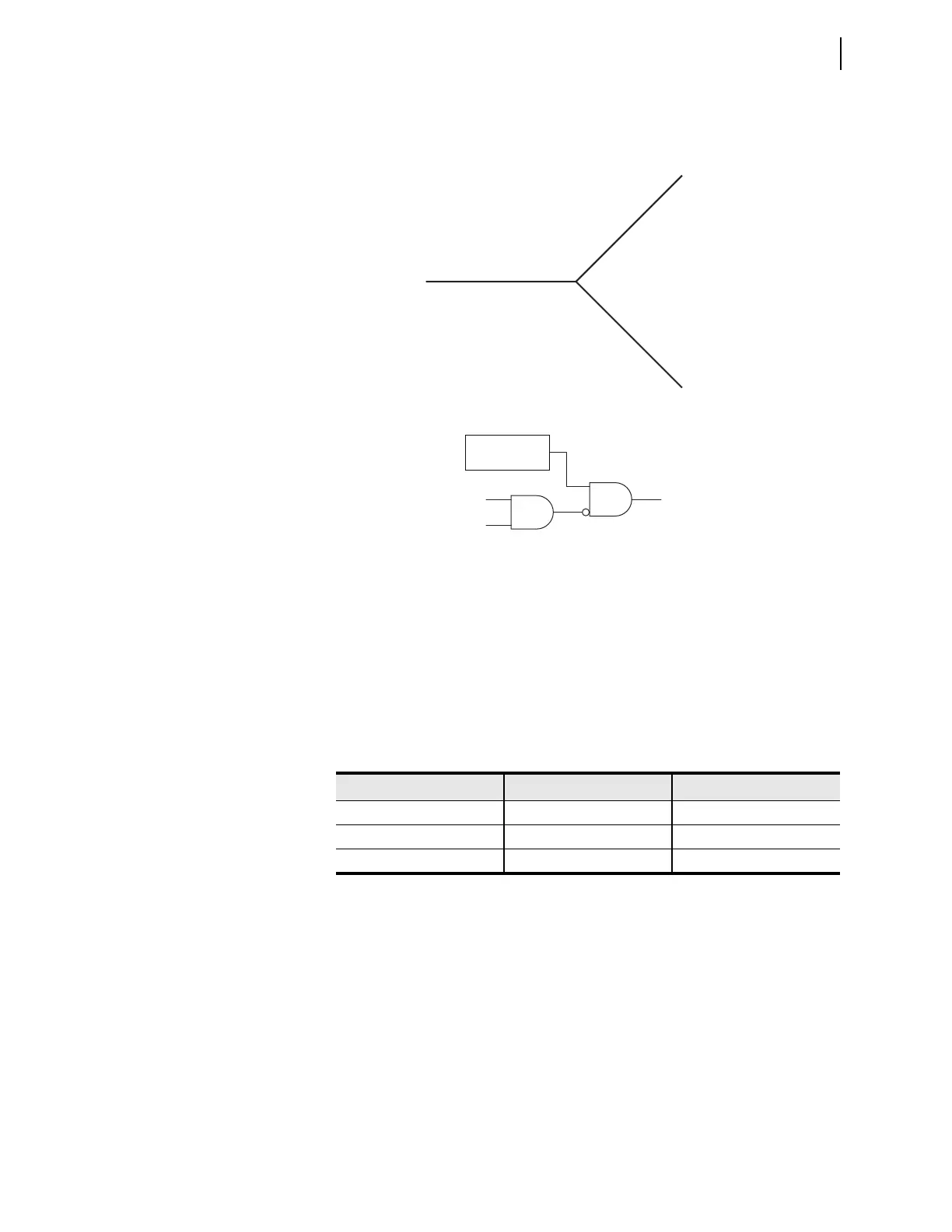
tion, and no system fault present. Figure 5.50 shows the blocking principle of the
A-Phase-to-ground mho element by the de-asserted OSBA signal.
The same principle applies to OSBB and OSBC. When all three poles are closed,
OSBA, OSBB, and OSBC are de-asserted and the distance elements can trip nor-
mal, even during a power swing.
In Figure 5.48, the logic is enabled when the zero-sequence supervisory direc-
tional overcurrent element (50GR or 50GF) and negative-sequence supervisory
directional overcurrent element (50QR or 50QF) pick up during a single pole-
open condition (SPO). Table 5.48 shows the input/output combinations of the
logic.
Phase Mho Element Reset Logic
If the OSB function is enabled and a power swing occurs, the OSB signal blocks
the phase-fault detectors, but not the ground-fault detectors. Therefore, to remove
the OSB signal and clear a fault that occurs during an OOS condition, the relay
must detect three-phase and phase-to-phase faults (see Figure 5.51).
Figure 5.49 I0/IA2 Angle Supervision During Pole-Open Situation
Figure 5.50 Blocking of the MAG Signal by the OSBA Fault Detection
Table 5.48 Input/Output Combinations of the Pole-Open OOS Blocking Logic
Gate Turned On Open Phase Phases to Block
AND 6 Phase A Phases B and C
AND 7 Phase B Phases A and C
AND 8 Phase C Phases C and A
A-Phase open
Normal IO/IA2 angle location
B-Phase
Normal IO/IA2 angle location
C-Phase open
Normal IO/IA2 angle location
MAG
Phase A-G
mho signal
OSB
OSBA
Ground A-to-G
distance logic