5.148
SEL-421 Relay Instruction Manual Date Code 20171021
Protection Functions
Circuit Breaker Failure Protection
Failure to Interrupt Fault Current: Scheme Y1
Circuit Breaker Failure Protection Logic
The logic shown in Figure 5.104 applies to single breaker configurations.
Scheme Y1 is similar to Scheme 1, but the current check (50FA1) is now part of
the Breaker Failure initiate timer (BFPU1) and Retrip Time delay (RTPU1) in
addition to the Breaker Failure initiate settings (BFI3P1 or BFIA1).
Failure to Interrupt Fault Current: Scheme 2
Scheme 2 actually consists of two discrete circuit breaker failure protection
schemes. The first scheme is applied for multiphase faults; apply a short time
delay on pickup prior to asserting the circuit breaker failure trip because three-
phase faults are the greatest threat to transient power system stability. The second
scheme is applied for single phase-to-ground faults; an additional timer is pro-
vided so you can coordinate retripping and circuit breaker failure tripping for the
different fault types.
Circuit Breaker Failure Protection Logic: Multiphase Faults
The logic diagram shown in Figure 5.105 applies to three-pole tripping for one or
two circuit breakers (EBFL = 2). Use this logic when the protected circuit
breaker fails following a three-pole trip from the line-relaying scheme.
Fault current causes 50FA1 (Breaker 1 A-Phase Instantaneous Overcurrent Ele-
ment) to assert immediately following fault inception and just prior to the asser-
tion of Relay Word bit BFIA1 (Breaker 1 A-Phase Circuit Breaker Failure
Initiation). At circuit breaker failure initiation, timer BFPU1 (Breaker 1 Circuit
Breaker Failure Time Delay on Pickup Timer) starts timing. If 50FA1 remains
asserted when timer BFPU1 expires and at least two of the three initiation Relay
Word bits BFIA1, BFIB1, or BFIC1 are asserted, Relay Word bit FBF1
(Breaker 1 Circuit Breaker Failure) asserts. (Two of three asserted initiation
Relay Word bits indicate a multiphase fault.) Use FBF1 in the circuit breaker fail-
ure tripping logic to cause a circuit breaker failure trip (see Circuit Breaker Fail-
ure Trip Logic on page 5.154). If the protected circuit breaker opens successfully,
50FA1 drops out before timer BFPU1 expires and Relay Word bit FBF1 does not
assert.
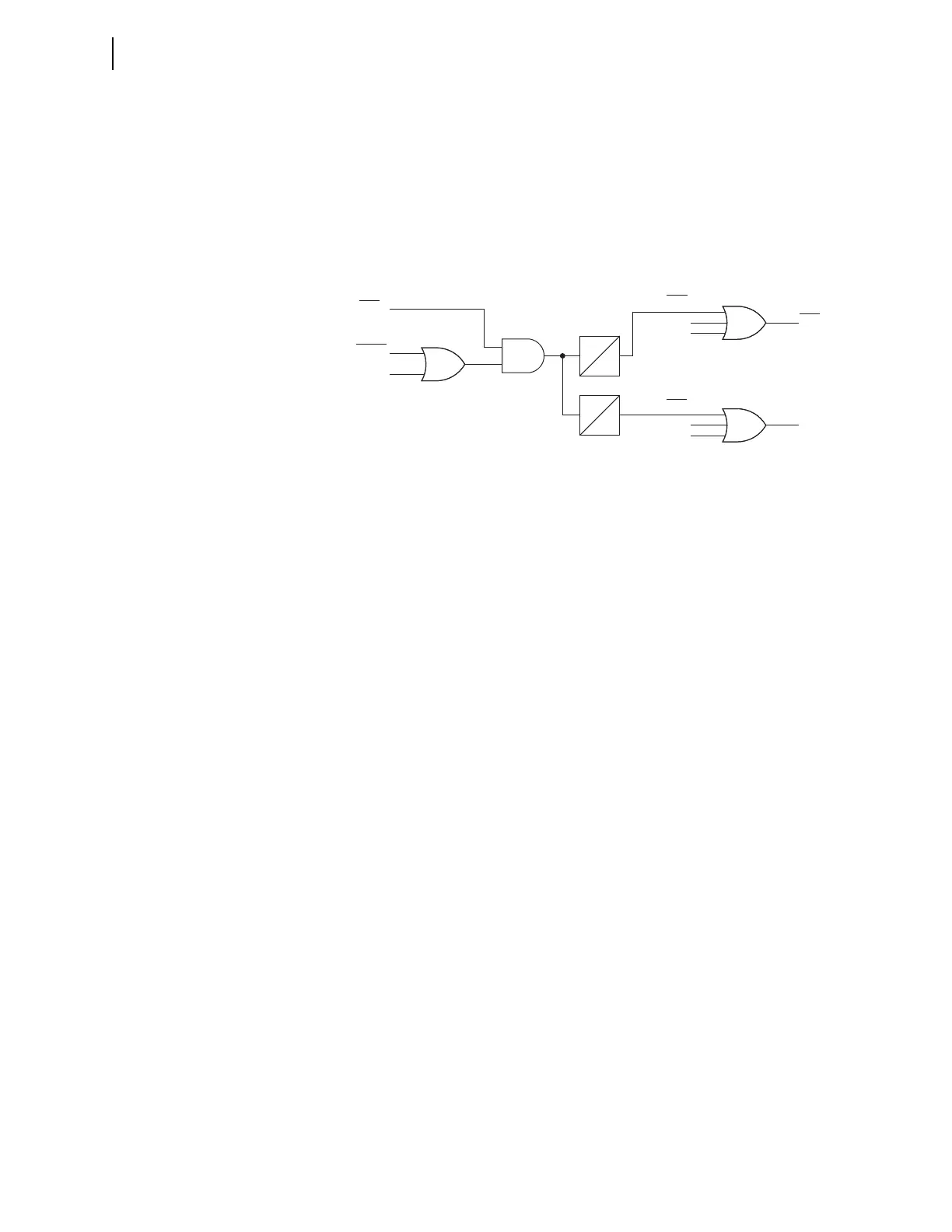
Figure 5.104 Scheme Y1 Circuit Breaker Failure Logic
BFPUn
0
RTPUn
0
FBFn
RTn
FBFBn
FBFAn
FBFCn
50FAn
BFI3Pn
BFIAn
RTBn
RTCn
RTAn
Relay
Word
Bits
Relay
Word
Bits
Relay
Word
Bits
Relay
Word
Bits
SELOGIC
Settings