6.44
SEL-421 Relay Instruction Manual Date Code 20171021
Protection Applications Examples
500 kV Parallel Transmission Lines With Mutual Coupling Example
The difficulty arises with the line protection at Station S prior to a circuit breaker
opening at Station R (after the circuit breakers open at Station R, the line protec-
tion at Station S identifies each fault as single phase-to-ground). This difficulty
diminishes as the fault location moves closer to Station S. At Station S, the relays
for Lines 1 and 2 misidentify the fault as ABG. If the permissive trip signal from
Station R arrives while an overreaching Zone 2 phase-to-phase distance element
at Station S is picked up, an undesirable three-pole trip results for both lines at
Station S. (An ABG fault involves more than one phase, so protection for this
fault must use three-pole tripping.)
To avoid this, you must make provisions for identifying the mismatch in fault
type identification between the line protection at both ends of the line. In doing
so, you avoid three-pole tripping both lines at Station S while single-pole tripping
both lines at Station R.
Transmit Equations
Overcoming this mismatch requires at least two communications channels, one
for transmitting three-pole trip permission (KEY3) and another for transmitting
all permissive trips (KEY1). The relay at Station S must receive both permissive
signals before three-pole tripping via the communications scheme. Thus, the
POTT2 scheme determines if there is agreement at both line ends on fault type
declaration. The relay checks fault type agreement by comparing the local fault
identification with the type of received permissive trip signal.
The Zone 2 phase-distance (Z2P) element asserts KEY1 and KEY3. The Zone 2
ground-distance (Z2G) element asserts KEY1 only. Use two separate signals,
rather than one, to send permission:
➤ KEY1—Transmit General Permissive Trip
➤ KEY3—Transmit Three-Phase Permissive Trip
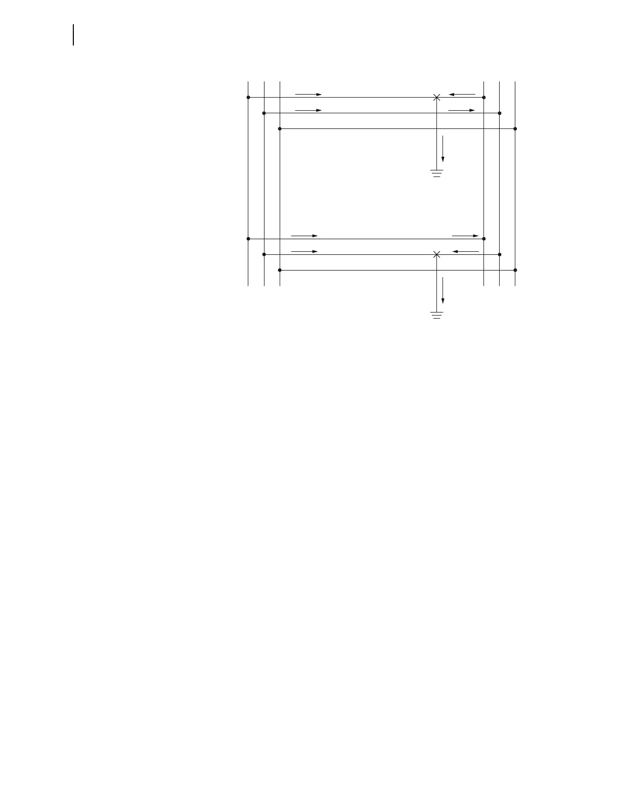
Figure 6.9 Current Distribution During Cross-Country Fault
LINE 1
LINE 2
I
AS1
I
BS1
I
AR1
3I
0(1)
3I
0(2)
I
BS1
I
BR2
I
AR2
I
BR2
ABC
SR
I
AR2