3.15
Date Code 20171021 Instruction Manual SEL-421 Relay
Testing
Checking Relay Operation
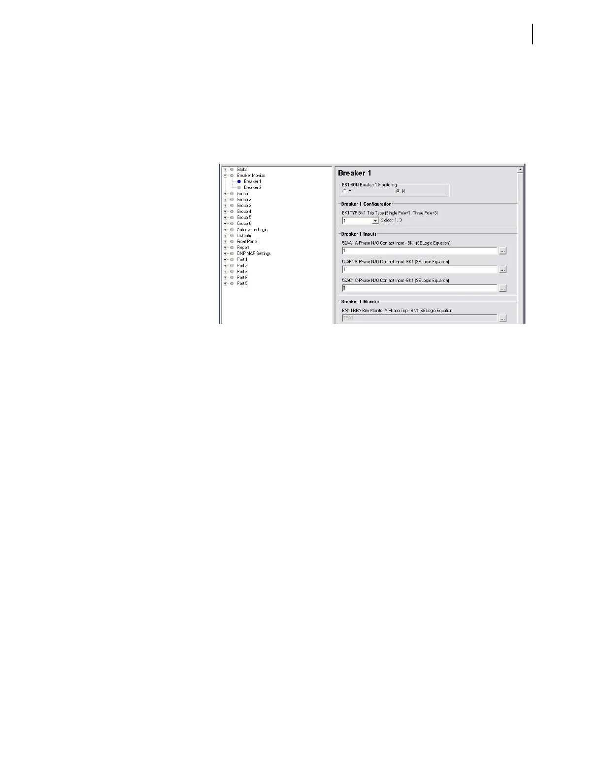
i. Enter 1 in the text boxes for 52AA1 A-Phase N/O Contact
Input -BK1, 52AB1 B-Phase N/O Contact Input -BK1, and
52AC1 C-Phase N/O Contact Input -BK1.
The text boxes in Figure 3.12 appear if Breaker Monitor setting
BK1TYP := 1.
j. If BK1TYP := 3, enter 1 in the 52AA1 N/O Contact Input -BK1
text box (the other circuit breaker input boxes are dimmed.)
Step 2. Set test values in the relay.
a. Expand the Group 1 settings as shown in Figure 3.13 and select
the Line Configuration button.
You will see the Line Configuration dialog box of Figure 3.13.
b. Confirm the default settings of Z1MAG at 7.80 and Z1ANG at
84.00.
c. Click the + mark next to the Relay Configuration branch to
expand that Settings branch.
d. Select the Directional button.
You will see the Directional dialog box similar to Figure 3.14.
e. Confirm the following settings: E32 is AUTO, ORDER is Q,
50FP is 0.60, 50RP is 0.40, Z2F is 3.90, Z2R is 4.00, a2 is 0.10,
and k2 is 0.2.
The dialog box is dim since there are no settings to change.
The relay calculates these numeric settings automatically
because E32 is set to AUTO.
f. If you need to change these settings, set E32 to Y.
Table 3.3 shows the calculations.
See Ground Directional Elements on page 1.18 for details on
these relay calculations.
Figure 3.12 Breaker 1 Breaker Monitor Settings: QuickSet