18.3
Date Code 20171006 Instruction Manual SEL-400 Series Relays
Synchrophasors
Synchrophasor Measurement
Synchrophasor Measurement
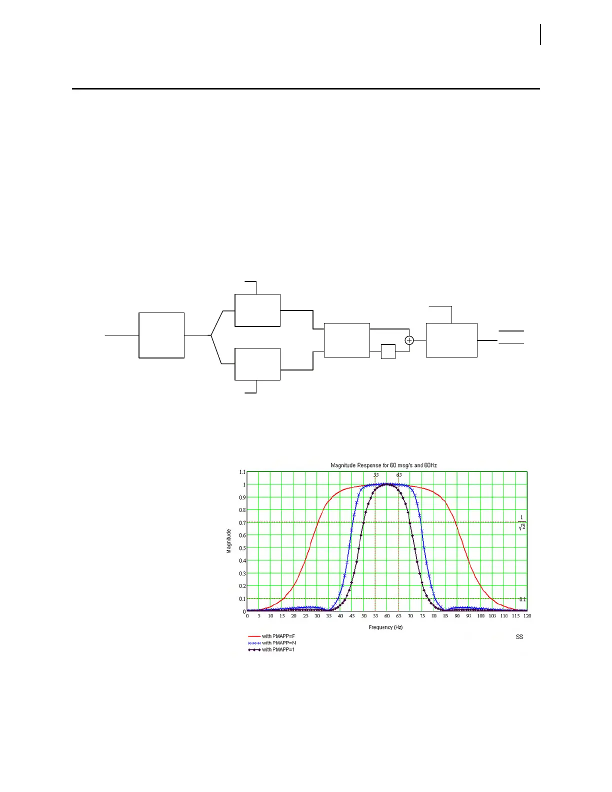
The PMU uses the signal processing shown in Figure 18.1 to measure the syn-
chrophasors. The input signal passes through a traditional anti-aliasing low-pass
filter (LPF). This filter has a cutoff frequency of 250 Hz. The PMU decimates
this 8 kHz filtered data by eight and then processes the resulting data at 1 kHz.
The PMU then modulates the 1 kHz data with two sinusoids, each 90 degrees
apart to produce real and imaginary components of the synchrophasor. The mod-
ulating sinusoids are synchronized to absolute time to provide an absolute time
reference for the synchrophasor. Also an angular compensation factor compen-
sates for the phase shift introduced by the PMU hardware and software.
The modulated data are filtered using low-pass filters. The filter coefficients are
based on NFREQ, PMAPP, and MRATE. The filtered data provides good attenu-
ation for harmonics and interharmonics. For PMAPP = F and N the attenuation is
20 dB. For PMAPP = 1 the attenuation is 40 dB.
Figure 18.2 shows the magnitude frequency response of the synchronized phasor
measurement for PMAPP = F, N, and 1 for MRATE = 60.
Figure 18.1 Synchrophasor Processing Block Diagram
V km
I kn
Filter A
Filter B
Time
FREQPM
Time
1 kHz
Data
Lowpass
Filter and
Decimate
to 1 kHz
8 kHz
Data
1 kHz
Real Data
1 kHz
Imaginary
Data
Downsample
to NFREQ
Magnitude
and Angle
Compensation
j
V km SF
I kn SF
Figure 18.2 Magnitude Frequency Response