5.175
Date Code 20171021 Instruction Manual SEL-421 Relay
Protection Functions
Synchronism Check
chronism-Check Voltage Source 2 (ASYNCS2) and corresponding settings
AKS2M and AKS2A for the regular Synchronism-Check Voltage Source 2 val-
ues SYNCS2, KS2M, and KS2A. The result is a normalized synchronism-check
voltage source V
S2
derived from the alternative source.
Example 5.1
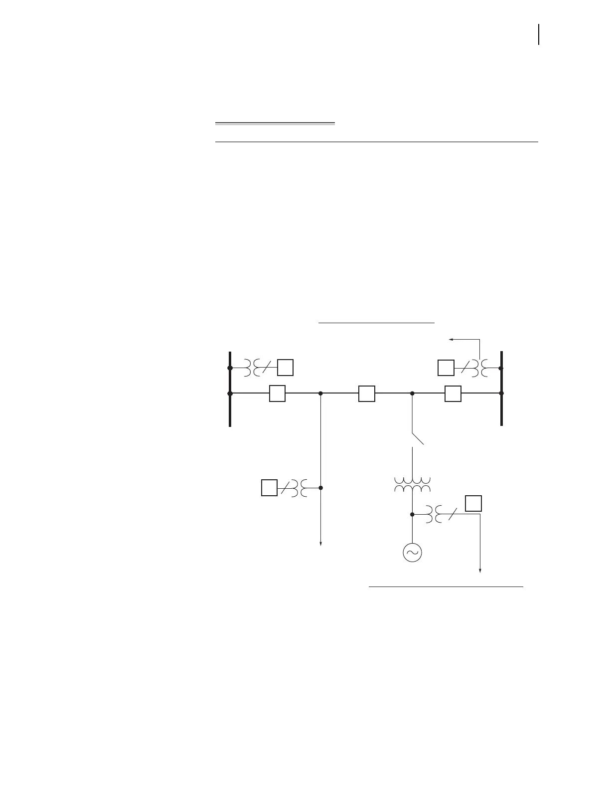
Figure 5.131 shows an extra circuit breaker (BK3) and a generator position
added to the existing example system of Figure 5.119. You can monitor the
voltage at the generator position by connecting a single-phase voltage to
remaining voltage input VCZ (see Figure 5.122). Make setting
ASYNCS2 := VCZ to designate this relay voltage input as the alternate syn-
chronism-check voltage source.
ASYNCS2 := VCZ. Alternative Synchronism Source 2 (VAY, VBY, VCY,
VAZ, VBZ, VCZ)
For this new synchronism source voltage connection, adjust the source-to-
reference magnitude ratio with setting AKS2M and the source-to-reference
angle compensation with setting AKS2A, considering the settings for Volt-
age Magnitude and Angle Compensation on page 5.163.
For example, in Figure 5.131, the Bus 2 voltage is the regular Synchronism-
Check Voltage Source 2 for synchronism check across Circuit Breaker BK2.
However, if Circuit Breaker BK3 is open and the generator switch is closed,
the Synchronism-Check Voltage Source 2 transfers to the alternative Syn-
chronism-Check Voltage Source 2 the voltage from the generator position.
Figure 5.131 Alternative Synchronism-Check Source 2 Example and Settings
Bus 1
Line
Switch
SYNCS2 — designate voltage input
KS2M — adjust magnitude to reference
KS2A — adjust angle to reference
Bus 2
BK2 BK3
BK1
Generator
Synchronism-Check Voltage Source 2
ASYNCS2 — designate voltage input
AKS2M — adjust magnitude to reference
AKS2A — adjust angle to reference
ALTS2 — enable alternative source 2
Alternative Synchronism-Check Voltage Source 2
1
3
1
1