6.95
Date Code 20171021 Instruction Manual SEL-421 Relay
Protection Applications Examples
EHV Parallel 230 kV Underground Cables Example
Employ each zone of distance protection as follows:
➤ Zone 1—Instantaneous underreaching direct tripping
➤ Zone 2—Forward-looking tripping elements for the POTT scheme
and backup tripping
➤ Zone 3—Current reversal guard for the POTT scheme, echo tripping,
and weak infeed logic
Zone 1 Reactance
The reach of the Zone 1 reactance measurement of the quadrilateral ground-dis-
tance elements must meet the same requirement as that for Zone 1 mho phase-
distance protection; the reach setting can be no greater than 80 percent of the
cable.
XG1 = 0.8 • |Z
1L1
| = 0.8 • 0.48 = 0.38
XG1 := 0.38. Zone 1 Reactance (OFF, 0.05–64 secondary)
Zone 1 Resistance
Find RG1 (Zone 1 Resistance) from the per-unit reach m of the Zone 1 reactance.
Use Equation 6.55, which is Equation 3 in Appendix A—Quadrilateral Reactive
Reach Versus Resistive Reach Setting Guideline from the paper Digital Commu-
nications for Power System Protection: Security, Availability, and Speed (go to
selinc.com for a copy of this paper):
Equation 6.55
XG1 is set at 80 percent of the underground cable (i.e., m = 0.8 per-unit); the pos-
itive-sequence reactance of the cable, X
1L1
, is 0.323 secondary (from the rect-
angular form of Z
1L1
in Table 6 .2 3).
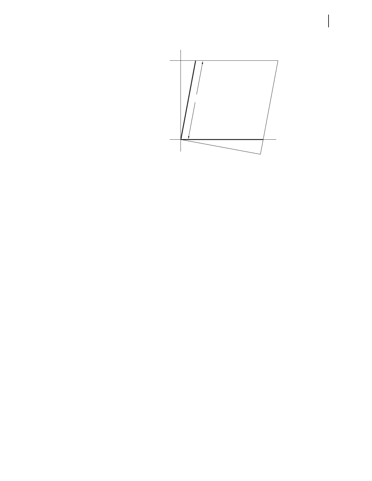
Figure 6.21 Quadrilateral Ground-Distance Element Reactive Reach Setting
where:
m = per-unit reach of XG1
R = RG1 (the Zone 1 resistance)
X
1L1
= positive-sequence transmission line reactance
m1
R
X
1L1
20•
-------------------------–=