2.48
SEL-421 Relay Instruction Manual Date Code 20171021
Installation
Connection
The following list provides additional rules and practices you should follow for
successful communication using EIA-232 serial communications devices and
cables:
➤ Route communications cables well away from power and control
circuits. Switching spikes and surges in power and control circuits
can cause noise in the communications circuits if power and control
circuits are not adequately separated from communications cables.
➤ Keep the length of the communications cables as short as possible to
minimize communications circuit interference and also to minimize
the magnitude of hazardous ground potential differences that can
develop during abnormal power system conditions.
➤ Ensure that EIA-232 communications cable lengths never exceed
50 feet, and always use shielded cables for communications circuit
lengths greater than 10 feet.
➤ Modems provide communication over long distances and give
isolation from ground potential differences that are present between
device locations (examples are the SEL-28XX-series transceivers).
➤ Lower data speed communication is less susceptible to interference
and will transmit greater distances over the same medium than higher
data speeds. Use the lowest data speed that provides an adequate data
transfer rate.
Ethernet Network Connections
The optional Ethernet card for the SEL-421 comes with two ports, either A and B
or C and D. You can use either installed port. These ports can work together to
provide a primary and backup interface. Other operating modes (FIXED and
SWITCHED) are also available. The following list describes the Ethernet card
port options.
➤ 10/100BASE-T. 10 Mbps or 100 Mbps communication using Cat 5
cable (category 5 twisted-pair) and an RJ45 connector
➤ 100BASE-FX. 100 Mbps communication over multimode fiber-optic
cable using an LC connector
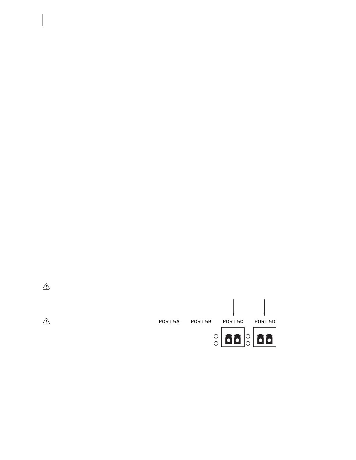
Ethernet Card Rear-Panel Layout
Rear-panel layouts for the three Ethernet card port configurations are shown in
Figure 2.49–Figure 2.54.
Figure 2.48 Example Ethernet Panel With Fiber-Optic Ports
Optional fiber-optic ports
Use of controls or adjustments, or
performance of procedures other
than those specified herein, may
result in hazardous radiation expo-
sure.
Do not look into the fiber ports/con-
nectors.