5.147
Date Code 20171021 Instruction Manual SEL-421 Relay
Protection Functions
Circuit Breaker Failure Protection
different breaker failure times to differentiate between single-pole and three-pole
tripping conditions. The failure-to-trip-load-current logic uses the circuit breaker
failure initiation input for three-pole trips only. The flashover protection logic
does not need voltage information.
Subsidence current results from the energy trapped in the CT magnetizing branch
after the circuit breaker opens to clear a fault or interrupt load. Subsidence cur-
rent exponentially decays and delays resetting of instantaneous overcurrent ele-
ments. However, the open-phase detection logic causes the relay 50Fn elements
to reset in less than one cycle during subsidence current conditions (see
Figure 5.114, Figure 5.115, and Figure 5.116). The open-phase detection logic
output is BnOPH (see Table 5.23).
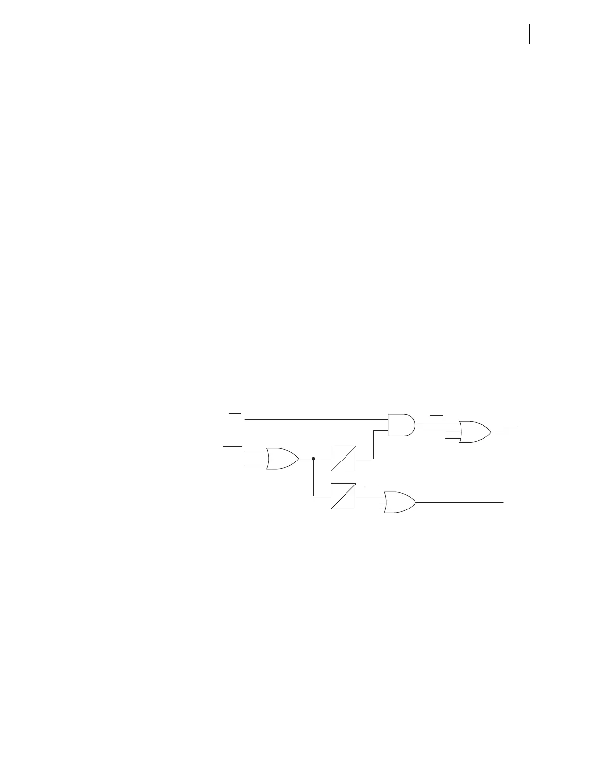
Failure to Interrupt Fault Current: Scheme 1
Circuit Breaker Failure Protection Logic
The logic shown in Figure 5.103 applies to single circuit breaker configurations
(EBFL = 1). Fault current causes 50FA1 (Breaker 1 A-Phase Instantaneous Over-
current Element) to assert immediately following fault inception and just prior to
the assertion of Relay Word bit BFI3P1 (Breaker 1 Three-Pole Circuit Breaker
Failure Initiation). At circuit breaker failure initiation, timer BFPU1 (Breaker 1
Circuit Breaker Failure Time Delay on Pickup Timer) starts timing. If 50FA1
remains asserted when the BFPU1 timer expires, Relay Word bit FBF1 asserts.
Use this Relay Word bit in the circuit breaker failure tripping logic to cause a cir-
cuit breaker failure trip (see Circuit Breaker Failure Trip Logic on page 5.154). If
the protected circuit breaker opens successfully, 50FA1 drops out before the
BFPU1 timer expires and FBF1 does not assert.
Retrip Logic
Some three-pole circuit breakers have two separate trip coils. If one trip coil fails,
the local protection can attempt to energize the second trip coil to prevent an
impending circuit breaker failure operation. Configure your protection system to
always attempt a local retrip using the second trip coil before the circuit breaker
failure pickup time delay timer expires.
RTPU1 (Retrip Time Delay on Pickup Timer) begins timing when BFI3P1
asserts. Relay Word bit RT1 (Breaker 1 Retrip) asserts immediately after RTPU1
times out. Assign a control output to trip the circuit breaker when Relay Word bit
RT1 asserts.
Figure 5.103 Scheme 1 Logic Diagram
BFPU1
0
RTPU1
0
FBF1
RT1
FBFB1
FBFA1
FBFC1
50FA1
BFI3P1
BFIA1
RTB1
RTC1
RTA1
Relay
Word
Bits
Relay
Word
Bits
Relay
Word
Bits
Relay
Word
Bits
SELOGIC
Settings